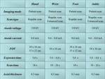
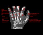
The physicotechnical conditions for scanning of distal extremities were worked up taking into consideration the minimization of an equivalent dose (Fig.
1).
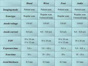
Fig. 1: CBCT-scan settings for distal segments of upper and lower extremities
All the CBCT-examinations were completed with the preliminary selection of the most comfortable patient's extremity positioning with an application of special x-ray negative positioning trays.
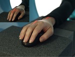
The examinations of hand and wrist were made while a patient was in sitting position behind the gantry using the special positioning trays.
The wrist was in the middle physiologic position.
The forearm and the wrist were adjacent to the table by its dorsal surface.
The decussation of laser beams for CBCT of the wrist is on the thirdmetacarpophalangeal articulation,
for examination of the hand – in the centre of the wrist joint (Fig.
2).
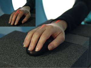
Fig. 2: Positioning of an upper extremity for CBCT-examinations of wrist and hand
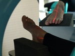
The examinations of the foot and the ankle were conducted when a patient’s position is sitting on the table.
For the foot scanning the extremity was standing on the plantar side on the positioning tray.
The decussation of laser beams is on the basis of the third metatarsal bone.
For the ankle examination a crus should be placed in parallel with the table.
In this case the decussation of laser beams is 1 cm upper the medial ankle-bone (Fig.
3).
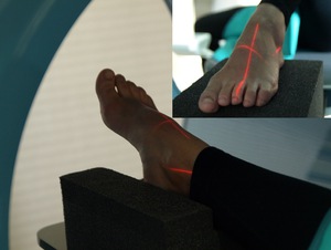
Fig. 3: Positioning of a lower extremity for CBCT-examinations of foot and ankle
Thereby,
the developed extremities positionings allowed to scan in the most informative,
physiologic and comfortable position.
The CBCT permits certainly visualize the soft tissues structures: muscles,
tendons,
ligaments,
aponeurosises,
big vessels,subcutaneous fatand skin.
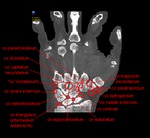
Due to this fact the normal cone-beam anatomy of distal region extremities was elaborated (Fig.
4,
5).
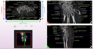
Fig. 4: CBCT. MPR, 3D. Left wrist. Normal cone-beam anatomy. White inscriptions – the bones, yellow inscriptions – the soft tissues.
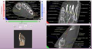
Fig. 5: CBCT. MPR. 3D. Right foot. Normal cone-beam anatomy. White inscriptions – the bones, yellow inscriptions – the soft tissues.
3D-visualization allows to determine the accessory bones avoiding the diagnostic faults that are possible using the two-dimensional radiography.
There are the locations of its possible disposition (Fig.
6,
7,
8,
9).
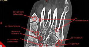
Fig. 6: CBCT. MPR, frontal view. The possible disposition of accessory bones of foot.
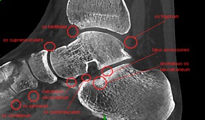
Fig. 7: CBCT. MPR, sagittal view. The possible disposition of accessory bones of foot.
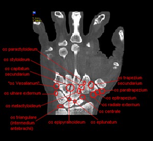
Fig. 8: CBCT. MPR, frontal view. The possible disposition of accessory bones of wrist.
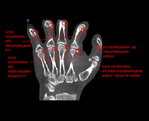
Fig. 9: CBCT. MPR, frontal view. The possible disposition of accessory bones of wrist.

