The average registration runtime was 2 h in MI-CC-SyN and 40 min in MI-demons-SyN implementations in 10 cases.
Quantitative evaluation: Landmark-based accuracy evaluation
The landmark feature points (128–292 points) were detected in the left and right lung in 10 cases.
The average distance and standard deviation (SD) of landmark feature points of the previous image and the corresponding current image (n = 10) as a reference standard for the accurate evaluation of diffeomorphic transformation was −0.42 mm in LR (left-right) (range,
−19.91 to 36.18 mm),
3.8 mm in AP (anterior-posterior) (range,
−18.53 to 25.62 mm),
and −3.66 mm in SI (superior-inferior) (range,
−27.47 to 10.68 mm).
The average distance and SD of landmark feature points of the previous image and the corresponding warped previous image by MI-CC-SyN was −0.43 mm in LR (range,
−19.91 to 36.18 mm),
3.8 mm in AP (range,
−18.53 to 25.56 mm),
and −3.68 mm in SI (range,
−27.61 to 10.69 mm).
The average distance and SD of landmark feature points of the previous image and the corresponding warped previous image by MI-demons-SyN was −0.52 mm in LR (range,
−20.32 to 35.61 mm),
3.81 mm in AP (range,
−18.53 to 25.22 mm),
and −3.68 mm in SI (range,
−27.24 to 10.68 mm).
Minimum and maximum Jacobian (logarithmic)
 The average Jacobian minimum was 0.31 and 0.15 in MI-CC-SyN and MI-demons-SyN,
respectively; the average Jacobian maximum was 3.74 and 10.8 in MI-CC-SyN and MI-demons-SyN,
and significant differences were found for the minimum Jacobian (P < 0.000004) and the maximum Jacobian (P < 0.003) by student t-test.
The average Jacobian minimum was 0.31 and 0.15 in MI-CC-SyN and MI-demons-SyN,
respectively; the average Jacobian maximum was 3.74 and 10.8 in MI-CC-SyN and MI-demons-SyN,
and significant differences were found for the minimum Jacobian (P < 0.000004) and the maximum Jacobian (P < 0.003) by student t-test.
Visual inspection for accuracy
Figures 1‒5 show the sample output of diffeomorphic transformation,
subtraction process (MI-CC-SyN and by MI-demons-SyN),
and volume change tracker (MI–CC–SyN and by MI–demons–SyN),
respectively.
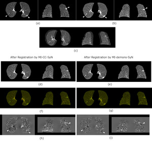
Fig. 1: Sample output of diffeomorphic transformation. The columns from left to right show the axial and coronal planes, respectively. The white arrows indicate the left lung lesion and the right lung latent lesion. (a) Previous images in the axial plane. The lengths of the long and short diameters of the left lung lesion are 33 and 20 mm, respectively. (b) Current images (interval of 4 months and 6 days). In the axial plane, the long and short diameters of the left lung lesion are 40 and 18.5 mm, respectively. (c) Overlapping of previous and current images (showing misregistration). The position of the lung surface shows a clear difference between previous and current volumes. (d) In the warped previous images by MI-CC-SyN, the long and short diameters of the left lung lesion are 33 and 20 mm, respectively. (e) In the warped previous images by MI-demons-SyN, the long and short diameters of the left lung lesion are 37.6 and 20 mm, respectively. Overlapping of the warped previous image and the current image (well-matched) by (f) MI-CC-SyN and (g) MI-demons-SyN. Red indicates the warped previous image and green indicates the current image. (h) and (i) Log-Jacobian images of the deformation field by MI-CC-SyN and MI-demons-SyN.
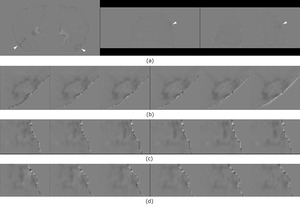
Fig. 2: Sample output of the subtraction process of Figure 1 after diffeomorphic transformation by MI-CC-SyN. The white arrows indicate the left lung lesion and right lung latent lesion. (a) Subtraction images were obtained by subtracting the warped previous images from the current images. The columns from left to right are the axial, sagittal, and coronal planes, respectively. Local enlarged subtraction images of the left lung lesion with six successive slices in the (b) axial, (c) sagittal, and (d) coronal planes (showing clear enhanced shadows). Decreased misregistration artifacts were noted, and the shadows of the lesions showed clear.
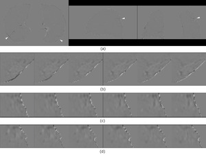
Fig. 3: Sample output of the subtraction process of Figure 1 after diffeomorphic transformation by MI-demons-SyN. The white arrows indicate the left lung lesion and right lung latent lesion. (a) Subtraction images were obtained by subtracting the warped previous images from the current images. The columns from left to right are the axial, sagittal, and coronal planes, respectively. Local enlarged subtraction images of the left lung lesion with six successive slices in the (b) axial, (c) sagittal, and (d) coronal planes (showing unclear enhanced shadows).
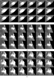
Fig. 4: Sample output of volume change tracker of Figure 1 after diffeomorphic transformation by MI-CC-SyN. (a)‒(c) Local enlarged images of lesion tissue with six successive slices and detailed comparisons of the morphological changes. In (a)‒(c), the above row shows lesions in the previous images, the middle row shows lesion in the current images, and the below row shows lesions in the warped previous images. The lesion in the warped previous image retained lesion morphology compared to the previous image.
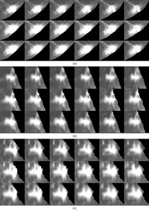
Fig. 5: Sample output of volume change tracker of Figure 1 after diffeomorphic transformation by MI-demons-SyN. (a)‒(c) Local enlarged images of lesion tissue with six successive slices and detailed comparisons of the morphological changes. In (a)‒(c), the above row shows lesions in the previous images, the middle row shows lesion in the current images, and the below row shows lesions in the warped previous images. While the lesion in the warped previous image shows grew compared to the previous image.
Figure 6 and Figure 7 show lesions were noted in the upper lungs.
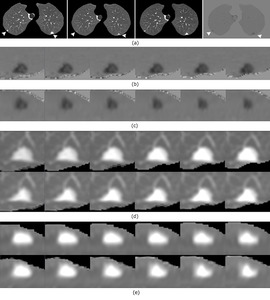
Fig. 6: Comparison of the alignments of small metastatic nodules in the upper lung after diffeomorphic transformation by MI-CC-SyN. White arrows indicate small metastatic nodules in the left upper lung and subtle latent lesions in the right upper lung. (a) Columns from left to right are the previous image (left upper lung nodule diameter, 14 mm), the current image (left upper lung nodule diameter, 10 mm), the warped previous image (left upper lung nodule diameter, 13.6 mm), and the subtraction image. (b) and (c) Local enlarged subtraction images of the left upper lung nodule with six successive slices in the axial and coronal planes, respectively. Clear enhanced shadows are seen in the subtraction images. (d) and (e) Local enlarged images of nodule with six successive slices and detailed comparisons of the morphological changes. In (d) and (e), the above row shows the nodule in the previous images, while the below row shows the nodule in the warped previous images. The nodule in the warped previous image retained its nodular morphology compared to that in the previous image.
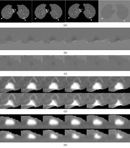
Fig. 7: Comparison of the alignments of small metastatic nodules in the upper lung after diffeomorphic transformation by MI-demons-SyN. White arrows indicate small metastatic nodules in the left upper lung and subtle latent lesions in the right upper lung. (a) Columns from left to right are the previous image (left upper lung nodule diameter, 14 mm), the current image (left upper lung nodule diameter, 10 mm), the warped previous image (left upper lung nodule diameter, 11.8 mm), and the subtraction image. (b) and (c) Local enlarged subtraction images of the left upper lung nodule with six successive slices in the axial and coronal planes, respectively. Unclear enhanced shadows are seen in the subtraction images. (d) and (e) Local enlarged images of the nodule with six successive slices and detailed comparisons of the morphological changes. In (d) and (e), the above row shows the nodule in the previous images, while the below row shows the nodule in the warped previous images. The nodule in the warped previous image showed shrinkage when compared to that in the previous image.
Figure 8 and Figure 9 show the sample output of volume change tracker indicated that the bigger lesion in the warped previous image showed shrinkage compared with that in the previous image by MI-CC-SyN and MI-demons-SyN implementations,
respectively.
Taken together,
regarding the warped previous image,
we found that MI-demons-SyN implementation caused more local shrinkage or expansion when the corresponding location in the current image had shrinkage or expansion than the previous image.
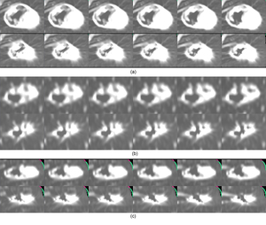
Fig. 8: Volume change tracker for one case showing lesion shrinkage changes with six successive slices in the three planes. (a)‒(c) The lesion in the axial, sagittal, and coronal planes, respectively. The above row shows the lesion in the previous images, while the below row shows the lesion in the warped previous images. Clear shrinkage of the lesion is seen in the warped previous image by MI-CC-SyN implementation compared with the previous image.
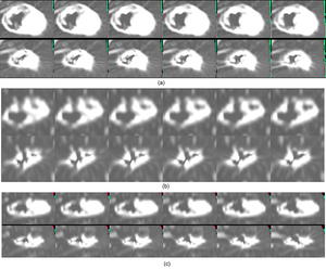
Fig. 9: Volume change tracker for one case showing lesion shrinkage changes with six successive slices in the three planes. (a)‒(c) The lesion in the axial, sagittal, and coronal planes, respectively. The above row shows the lesion in the previous images, while the below row shows the lesion in the warped previous images. More shrinkage of the lesion is seen in the warped previous image by MI-demons-SyN implementation compared with the previous image.
