ANATOMY
The orbit is a unique structure that has the primary purpose of housing and protecting the globe.
By age 5 years,
orbital growth is 85% complete; growth is finalized between 7 years of age and puberty.
The orbit is a four- sided pyramid with its apex at the optic foramen; anteriorly its base is formed by the orbital rim.
The orbital rim consists of dense cortical bone that protects the orbital contents from direct trauma.
Seven bones contribute to the formation of the orbit: maxillary,
zygomatic,
frontal,
ethmoidal,
lacrimal,
platine and sphenoid.
Fig. 1
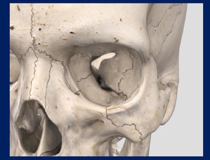
Fig. 1: Orbital overview.
The roof of the orbit consists largely of the orbital plate of the frontal bone.
It is thin and separates the orbit form the anterior cranial fossa.
In the elderly,
the orbital roof may become resorbed,
resulting in areas where the periorbita becomes fused to the overlying dura.
This finding should not be mistaken with a fracture.
At the junction of the medial one third and lateral two thirds of the superior rim lies the supraorbital notch,
which is often converted to a foramen (in 25% of individuals).
The thin orbital floor (often only 0.5 mm thick),
separates the maxillary sinus from the orbital contents.
Is defined posterolaterally by the sphenomaxillary fissure.
The orbital surface of the maxilla and the ethmoid bone contribute to the floor and medial wall and articulate with the lacrimal bone in the nasoethmoidal region.
The infraorbital canal opens 5 mm below the rim of the maxilla as the infraorbital foramen. Fig. 2
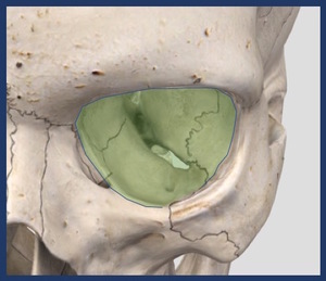
Fig. 2: Floor of the orbit.
The lateral wall of the orbit is composed of the greater wing of the sphenoid bone and the frontal process of the zygoma.
This is the strongest wall,
but it may be fractured along its thinnest portion of the suture line,
where the greater wing of the sphenoid and zygoma join.
This wall separates the orbit from the temporalis muscle.
Lateral wall involvement is a hallmark of zygoma fractures. Fig. 3
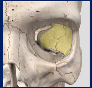
Fig. 3: Lateral wall of the orbit.
The medial wall of the orbit is by far the most complex.
Arranged anteriorly to posteriorly,
it consists of a portion of the frontal,
lacrimal,
ethmoid and sphenoid bones.
The orbital surface of the ethmoid or lamina papyracea is extremely thin (0.2-0.4 mm) and forms the largest section of the medial wall.
Fig. 4
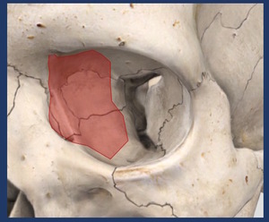
Fig. 4: Medial wall of the orbit.
The medial wall and roof join at the frontoethmoidal suture,
an important landmark for implant positioning and the site of the anterior (20 mm behind the orbital rim) and posterior ethmoidal artery foramina.
(12 mm further back).
They mark the level of the cribiform plate and should be carefully visualized if a CSF leak is suspected.
It articulates with the orbital floor and the medial wall of the maxillary sinus to form a thick septum called the internal orbital buttress.
At the apex,
the lesser wing of the sphenoid supports the orbital plate of the palatine bone,
forming the posterior ledge used to seat orbital implants.
The globe lies in the anterior orbit.
Posterior to the globe,
the six extraocular muscles and their intermuscular fascial membranes form an intraorbital conical structure.
Veins and lymphatics lie within the orbital fat of the muscle cone.
Centrally,
the optic nerve sheath passes from the posterior globe to the brain.
The optic nerve sheath is an extension of the dura mater and contains the ophthalmic artery,
the optic nerve,
and small veins.
FRACTURE PATTERNS
The orbital walls vary in thickness and strength.
Fractures of the anterior and middle thirds of the orbit are common,
with the maxillary sinuses and ethmoid air cells serving as shock absorbers and acute volume expansion compartments.
As a result,
globe perforation and acutely increased intraocular pressure are relatively infrequent.
Except in severe life-threatening trauma,
fractures occurring in the posterior one third of the orbit are rare.
It is these fractures that can more commonly result in blindness,
Orbital fractures are roughly classified in two main groups:
Isolated Internal Orbital:Those limited to the internal orbital walls.
4-16% of facial fractures. Fig. 5
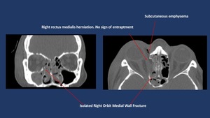
Fig. 5: Non-enhanced CT scan shows isolated linear medial orbit fracture with associated subcutaneous emphysema.
Combined:Those associated with other fractures of the orbital framework (Naso-orbito-ethmoid (NOE),
Frontal or the Zigomatico-maxillary complex).
30-55% of facial fractures. Fig. 6
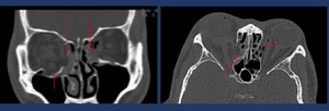
Fig. 6: Non-enhanced CT-Scan shows a bilateral medial wall fracture (long arrows) with subcutaneous emphysema and right floor of the orbit fracture (short arrow) with inferior displacement without entrapment of the inferior rectus muscle.
Zygomatic complex fractures are the most commonly occurring facial fracture,
second only to nasal fractures.
These fractures are also the most commonly fractures of the orbit.
Various classifications systems have been reported such as Zingg´s classification .
Zingg classification is a simple,
surgically relevant CT-based grading system.
Classifies injuries into three basic types,
each with its own considerations regarding surgical approach,
risks,
and benefits.
- Zingg type A fractures are isolated incomplete fractures involving only one limb of the zygoma.
- Zingg type B fractures are classic tetrapod fractures,
with a completely liberated zygomatic monofragment.
Fig. 7
- Zingg type C fractures are comminuted.
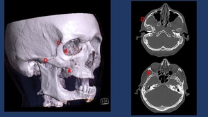
Fig. 7: The tetrapod-shaped ZMC fragment dissociates from the midface at four major points of failure: (A) the zygomaticomaxillary buttress from the inferior margin of the crest to the inferior orbital rim, (B) the zygomaticosphenoid suture along the lateral orbital wall, (C) the frontozygomatic suture of the lateral orbital rim, and (D) the zygomaticotemporal suture of the zygomatic arcH
NOE fractures most often occur following blunt trauma to the midface.
These fractures result primarily in cosmetic deformities such as flattening of the nasal dorsum and widening of the intercanthal distance.
The severity of these fractures can range from minimal displacement of a large segment of the orbital rim to swvere comminution. Fig. 8
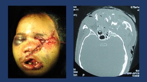
Fig. 8: Complex mid face fracture after high energy impact. CT shows NOE and left Zigomatic conminuted fractures with eye globe disruption.
Three patterns of internal orbital have been described: linear,
blow-out and complex.
Approximately 80% of isolated orbital fractures are “blow-out” fractures. They are limited to one wall,
with a defect of less than 2 cm in diameter.
They are usually caused by an object (eg a fist) larger than the orbital frame hiting the eye globe.
This causes an inward displacement of the eyeball exerting a great pressure over the medial and inferior orbital walls.
This kind of fractures should always be suspected when the victim reports diplopia and infraorbital nerve distribution numbness after receiving a concentrated direct blow in the eye.
Complex fractures consist of extensive fractures that affect two or more orbital walls; they often involve the posterior orbit and may involve the the opstic canal.
Complex fractures are usually associated with fractures of the facial skeleton outside the orbital frame (LeFort II and II fractures or frontal sinus fractures) which are classified as combined fractures. Fig. 9 Fig. 10Fig. 9
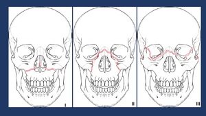
Fig. 9: Le Fort 1 fractures involve the lateral and medial walls of the maxillary sinus, propagating posteriorly from the piriform aperture.
Le Fort 2 fractures involve the frontonasal suture, the inferior orbital rim and floor, and the maxillary sinuses, forming a pyramidal shape.
The Le Fort 3 fracture level extends horizontally from the frontonasal suture to the frontozygomatic suture and zygomatic arches .
References: Synthes AO
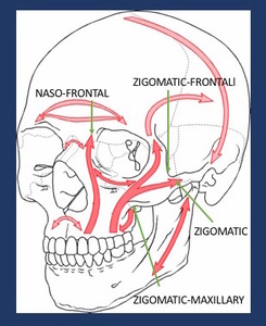
Fig. 10: Schematic representation of the facial buttresses. Depicted are the zygomatic and nano frontal buttresses, commonly involved in combined orbital fractures.
References: Synthes AO
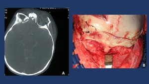
Fig. 11: A. CT-Scan shows bilateral roof of the orbit fracture associated with frontal fracture in a 2 year old child. B. Intraoperative picture showing open reduction and rigid fixation of the orbital fracture by means of resorbable plates to reduce the disturbance of the future growth of the face/skull.
In children we can find from time to time a different type of pure orbital fractures,
called “blow in” fractures. In these cases,
due to flexibility of the bone in growth,
a transient displacement of the orbital floor recovering inmediately its initial position can cause an impingement of the periorbita with a restriction in the eyeball extraocular movements without an apparent fracture.
When a fracture of the naso-ethmoidal,
zygoma complex or frontal bone is suspected,
greater focus should be made in order to assess a most likely concomitant orbital fracture.
CLINICAL SIGNS OF ORBITAL FRACTURES
- Swelling
- Hematoma
- Extraocular muscles entraptment: diplopia and eyeball movement restriction Fig. 12
- Numbness in the sensory area of the infraorbital/supraorbital nerve.
- Exophtalmia or enophtalmia
- Subcutaneous emphysema Fig. 13
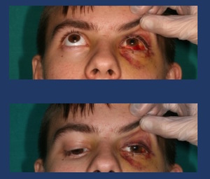
Fig. 12: Extra ocular movement exploration shows a restricted infraduction and supraduction of the left eye secondary to a floor of the orbit fracture with inferior rectus muscle entrapment.
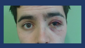
Fig. 13: Clinical signs of orbital floor fractures: subcutaneous emphysema, enophtalmos, red eye and periorbital swelling.
PREOPERATIVE IMAGING TECHNIQUES
Imaging is essential for the proper diagnosis and treatment of orbital trauma.
Radiographic examination of the orbits is rarely performed nowadays.
Radiography has a sensitivity of 64%–78% for a fracture,
but it has very low sensitivity for soft-tissue injuries to the orbital contents.
Several views may may be useful in evaluating orbital injury.
Caldwell´s projection provides a good view of the superior and lateral orbital rim.
Water´s projection allows visualization of the orbital roof and floor and is useful when evaluating blow-out fracture Fig. 14 .
Hirtz´s projection may be useful to assess isolated zygoma arch fractures Fig. 15 .
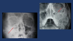
Fig. 14: Plain film findings include orbital enphysema, a fluid level in the maxillary sinus, misalignment of the orbital floor on Water’s view and soft tissue representing prolapsed orbital content in the superior aspect of the maxillary sinus.
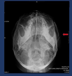
Fig. 15: Hirtz´s projection shows a left zygomatic arch fracture.
Ultrasonography (US) can be very useful for evaluating the globe and its contents; however,
US is contraindicated if a ruptured globe is suspected.
Magnetic resonance (MR) imaging may be difficult to perform emergently; it is contraindicated if there is a possibility that a metallic intraorbital foreign body is present.
Using MR imaging for the initial evaluation of an orbital trauma is not recommended,
although it may be very useful once the initial imaging has been performed.
MRI has been used to identify wood and foreign bodies that have been misdiagnosed by CT scan as Wood can appear isodense with fat and air on CT.
Non-contrasted CT is the primary imaging modality of choice in evaluating orbital trauma.
The goal of optimized CT is to help the radiologist make an accurate diagnosis while limiting the amount of radiation exposure to the lens.
The best protocol is to obtain thin-section axial CT scans (0.625–1.25 mm),
depending on the capabilities of the scanner) and afterwards perform multiplanar reformation.
Acquired helically from top of frontal sinus to hard palate. Iterative reconstruction in soft tissue and bone kernels on coronal oblique (perpendicular to CN II) and sagittal oblique(parallel to CN II)views.
Parameters: 120 kVp,
100 mAs,
1.25-mm section thickness with1.25-.mm intervals.
Navigation Protocols are recommended as more surgical teams are incorporating neuro navigation for orbital fracture treatment.
Fig. 16
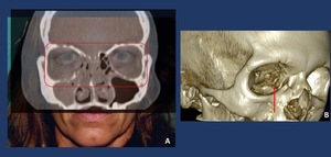
Fig. 16: A: Picture + TC Superimposition allows the clinician to evaluate the asymmetry of the orbital volumes. B: Bone reconstructions of the medial orbit Wall often tend to the show the bone perforate as an artifcat due to its thinnes
Soft tissue injuries such as lens dislocation,
vitreous hemorrhage,
ruptured globe,
retrobulbar hemorrhage or avulsion of the optic nerve are readily demonstrated by CT.
CT is also the modality of choice in detecting and localizing most metallic and nonmetallic foreign bodies in relation to the globe,
extraocular muscles and optic nerve.
The extent and size of subperiosteal hematomas may also be delineated with CT images.
CT scan has been shown to be more accurate than radiography in detecting fractures.
When fractures are present,
three-dimensional reformation is a useful tool to guide treatment.
Two main issues should be evaluated: Risk of developing late enophatlmos and extraocular movement restriction due to muscular entrapment.
1.
Enophtalmos Assessment
- High risk CT features for clinically important late enophthalmos include:
- Surface area greater than 2 cm2
- More than 25%–50% orbital floor or medial wall involvement
- Collapse of the junctional bulge and internal orbital buttress
- Soft-tissue herniation with volume displacement greater than 1.5 mL
In patients at risk for developing noticeable enophthalmos (2–3 mm),
reconstruction is performed in a semidelayed fashion before architectural changes have set in,
to restore the preinjury orbital shape and volumen.
Fig. 17
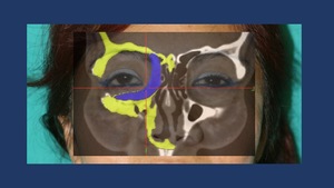
Fig. 17: Planning of a custom made implant for the medial wall and floor of the right orbit to treat an enophtalmus deformity secondary to inadequate initial reduction of the combined orbit fractures.
Mirroring postprocessing techniques with the healthy orbit allows the Radiologist/Craniofacial Surgeon to asses the change of orbital volume in the fractured orbit. Besides,
when available,
can help design custom-made implants to restore the previous anatomy. Fig. 18
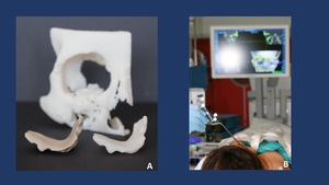
Fig. 18: A. Custom made HRT (Hard Tissue Replacement) implant designed to restore the loss of volume of the right medial wall and floor of the orbit. B. Intraoperative navigation to ensure a proper placement of the designed implant.
2.
Diplopia and Restricted Mobility
Diplopia is usually self-limiting,
owing to temporary muscle paresis and contusion,
which causes enlargement and rounding at CT.
Because muscle incarceration and necrosis are exceedingly rare in adults,
there is usually no surgical urgency.
However,
if a clear rectus muscle entrapment is visualized,
it should be noticed readily to the Craniofacial Surgeon,
as this is probably the only emergency in orbital fracture repair apart form severe globe disruption,
orbital hematoma or optic nerve compression.
In this sense,
it has been demonstrated that the latter (>24h) the muscle entrapment release,
the worse in terms of muscle recovery .
Tethering may resolve as the orbital edema improves,
and CT findings must be assessed together with the results of serial examinations.
Fig. 19 Fig. 20
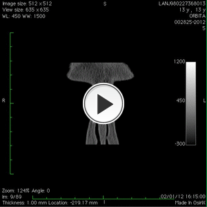
Fig. 19: Video of a CT-Scan Coronal reconstruction shows a left floor of the orbit fracture with inferior rectus muscle entrapment with periobital impingement.
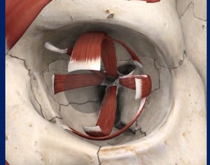
Fig. 20: Extraocular muscles scheme.
POSTOPERATIVE EVALUATION
It is beyond the scope of this presentation to review in detail all the different reconstructive techniques available to treat the orbital fractures.
The basic principles common to all of them rely on releasing the tissues prolapsed/entrapped in the orbital defects and bridging the bony defects in order to restore the orbital volume and avoid re-displacement of the orbital content into the bony defects.
Besides ORIF techniques are used to openly reduce and rigidly fixate the bone fragments of combined orbital fractures such as zigomatic fractures. Fig. 22 Fig. 21
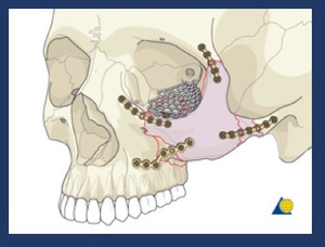
Fig. 22: Scheme of the ORIF techniques to fixate a tetrapod zygoma fracture and floor of the orbit repair with a titanium mesh.
References: AO Osteosynthesis Research Group
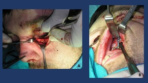
Fig. 21: ORIF Techniques with open reduction and internal fixation. A: inferior orbital rim titanium plate with floor of the orbit exposure. B: Internal fixation of the zygomatic-maxillary buttress.
Different biomaterials have been used to reconstruct the bony defects. The implant should ideally bridge the entire defect and rest on all bony edges.
Classically bone grafts form the calvaria or the iliac crest were used.
Calvaria grafts,
obtained from the outer diploe of the right parietal bone are visualized in the CT as small blocks of cortical bone.
Iliac bone grafts,
tend to be less dense.
Less frequent,
rib cartilage grafts have been used in anophtalmic orbit reconstruction.
These type of grafts were commonly secured with alluminum-alloy wires.
Besides if a NOE fracture with telecanthus has been repaired,
care must be taken to check if a transnasal canthal wiring has been used.
In these cases,
MRI should be avoided unless absolutely necessary.
Fig. 23
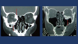
Fig. 23: Two different coronal CT-scan reconstruction showing multiple radio dense objects brick shaped used to treat combined orbital walls fractures. The objects are calvarial graft blocks. Osteosynthesis material is also viewed.
Other materials seldomly used included PDS sheets,
Silicone sheets and Porous Methylene implants.
Nowadays,
the mostly used type of implants are titanium stock orbital plates. They usually have two aspects for the medial wall and the orbital floor and of screw holes to secure the implant to the orbital rim. Prefabricated stock implants typically come in two sizes,
and selection of the appropriate implant is based on estimation of the defect size with CT.
New postprocessing techniques allow for titanium custom made implants manufacture and navigation protocols when available.
This allows the surgeon to restore the volume of the orbit in a more precise way. Fig. 24
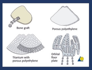
Fig. 24: Pictorial representation of the different types of materials used to bridge bony defects in orbital wall fractures.
References: AO Ostheosynthesis Research Group
Postoperative CT may identify correctable volume changes or entrapment related to the reconstruction,
prompting revisión.
Incomplete defect bridging caused bya a size mismatch or excessive angulation into the ethmoids or maxillary sinuses can cause orbital volume changes or impingements between mesh and bone edges.
Fig. 25 Fig. 26
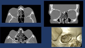
Fig. 25: Postoperative CT-scan of medial wall orbit fracture repaired with a titanium orbital mesh. Radiological report should include the posterior reach of the Titanium mesh (proximity to the optic nerve) and if present, extra ocular muscle impingement.
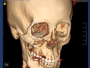
Fig. 26: CT.Scan 3D Volume Rendering shows osteosynthesis material in the right zygoma and a titianium mesh in the floor of the orbit.
Large medial wall defects extending to within 1 cm of the optic canal at CT require careful implant placement to avoid optic nerve impingement.
Rare postoperative complications include retrobulbar hematoma and orbital cellulitis.
Implant migration or extrusion is extremely rare. Fig. 27
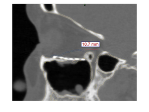
Fig. 27: CT-scan non enhanced, sagital reconstruction shows titanium mesh in the floor of the orbital malpositioned (too inferior).


 and if present, extra ocular muscle impingement.")
 with subcutaneous emphysema and right floor of the orbit fracture (short arrow) with inferior displacement without entrapment of the inferior rectus muscle.")


 implant designed to restore the loss of volume of the right medial wall and floor of the orbit. B. Intraoperative navigation to ensure a proper placement of the designed implant.")


 the zygomaticomaxillary buttress from the inferior margin of the crest to the inferior orbital rim, (B) the zygomaticosphenoid suture along the lateral orbital wall, (C) the frontozygomatic suture of the lateral orbital rim, and (D) the zygomaticotemporal suture of the zygomatic arcH")


.")