Commonly encountered artifacts on MRI due to CSF circulation are as follows:
I) GHOST ARTIFACTS
Phase mismapping or ‘Ghosting’ is a most common artifact due to CSF circulation.
It is recognized by the replication ('ghosts') of the moving anatomy across the image in the direction of the phase encoding gradient (4).
Cause:
The time duration during the acquisition of adjacent points following the application of the phase encoding gradient (PEG) is long (equal to the repetition time used).
During this time,
changes in the position of anatomy cause a phase difference between the views in k-space,
leading to misrepresentation across the field of view (4,5).
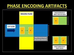
Fig. 2: Diagrammatic representation of the genesis of phase encoding artifacts. Changes in the position of anatomy during the phase encoding gradient lead to a phase difference in the k-space causing false representation or ‘ghosts’.
References: Dr. Vivek Pai
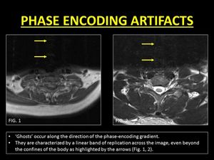
Fig. 3: Examples of phase encoding artifacts due to CSF motion.
References: Department of Radiology, SevenHills Hospital, India
Remedies:
As 'ghosts' occur along the direction of the PEG,
changing the orientation of the artifact by swapping the directions of the phase and frequency encoding gradients displaces the artifact from the region of interest.
Frequency encoding is resistant to these artifacts as the duration of application of the gradient is short (order of microseconds) and is applied only during the time of signal read-out (1,
4).
Secondly,
the use of shorter TR and hence shorter duration of PEGs helps in reducing the intensity of the artifacts.
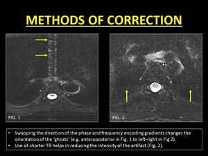
Fig. 4: Methods of correction of phase encoding artifacts.
References: Department of Radiology, SevenHills Hospital, India
Clinical Significance:
'Ghosts' are seen across the image even beyond the margins of the spinal canal.
These band-like artifacts can obscure lesions within the cord and the spine and hence need to be eliminated (5).
II) TIME-OF-FLIGHT (TOF) RELATED SIGNAL LOSS
To generate a signal,
protons must receive an initial excitation radiofrequency (90°) and a subsequent refocusing pulse (180°) (6).
In a spin-echo sequence,
these pulses are applied selectively to each slice and thus mobile protons in CSF may not experience one or both of the pulses necessary to contribute to a signal.
As a result,
an area of signal loss is seen (4).
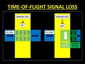
Fig. 5: Diagrammatic representations of the mechanism of Time-Of-Flight (TOF) signal loss. In order to generate a signal, protons must receive both 90° and 180° pulses. Thus mobile protons which move out of the imaging slice between the 2 pulses are unable to generate signal.
References: Dr. Vivek Pai
TOF loss is more prominent if the velocity of the CSF increases (for eg.
when images are acquired in systole) (1).
TOF loss is also more conspicuous in sequences with a longer TE (increased duration between the application of the 90° and 180° pulses) causing more protons to exit the imaging plane (1,4).
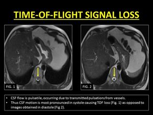
Fig. 6: TOF loss due to effects of pulsatile CSF motion.
References: Department of Radiology, SevenHills Hospital, India
Remedies:
The logical method to eliminate this artifact is to ensure the mobile protons experience both the 90° and 180° pulses.
This can be achieved by using thicker slices (1).
Shorter TE techniques (e.g.
true fast imaging with steady-state precession) are excellent in the correction of this artifact but have limited use in spinal imaging.
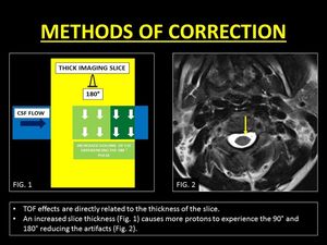
Fig. 7: Method of correction of TOF loss with the help of thicker imaging slices.
References: Dr. Vivek Pai and Department of Radiology, SevenHills Hospital, India
Another important method of troubleshooting is the acquisition of gradient echo sequences.
These sequences employ a slice selective excitation pulse followed by the application of a refocusing pulse to the entire volume.
Thus,
flowing protons that receive an excitation pulse are refocussed regardless of the slice position.
In addition,
the short TR in gradient echo sequences saturates stationary protons increasing contrast with flowing CSF (4).
Clinical Significance:
TOF loss is common in the imaging of the cervical spine.
In the clinical setting of trauma,
the artifact is notorious to mimic subarachnoid hemorrhage.
A dependent layering of T2W hypointense contents within the spinal canal and blooming on GRE images help to identify blood and distinguish it from TOF loss (7).
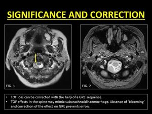
Fig. 8: Pitfalls and correction of TOF loss.
References: Department of Radiology, SevenHills Hospital, India
III) ENTRY SLICE PHENOMENON (ESP):
90° pulses cause the magnetic moments of protons to be flipped in the spin-down orientation.
When applied at short intervals (short TR),
the time for longitudinal recovery of the spins is inadequate leading to saturation.
Fresh inflowing protons have magnetic moments oriented in the spin-up directions,
thus imparting a signal (hyperintense) different from the rest of the stationary tissues (4).
With successive slices,
the hyperintense signals reduce as the flowing protons receive multiple excitation pulses as they traverse the imaging volume.
This phenomenon of hyperintensity only in the first few slices is termed as Entry Slice Phenomenon (4).
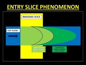
Fig. 9: Entry Slice Phenomenon results in a bright signal in the initial images of the stack which gradual fading. This occurs as a result of unsaturated spins flowing into the imaging plane which are flipped into the transverse plane emitting signals. Progressively, the spins get saturated as they experience repeated pulses and hence do not contribute to bright signals.
References: Dr. Vivek Pai
The magnitude of the ESP is dependent on the following parameters (4):
1.TR: A shorter TR increases the number of the excitation pulses,
causing protons to reach a state of saturation faster,
therefore,
decreasing the magnitude of ESP.
2.Slice thickness: Thicker slices ensure a larger volume of the CSF is subjected to the excitation pulse thus decreasing the magnitude of ESP.
3.Flow velocity: With faster moving protons,
the likelihood of receiving the excitation pulse is reduced,
increasing the magnitude of ESP.
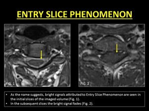
Fig. 10: Demonstration of Entry Slice Phenomenon.
References: Department of Radiology, SevenHills Hospital, India
Remedies:
As described the ESP is can be reduced with the use of shorter TR and thicker slices.
The trade-off with the use of these manipulations is a longer scan time with short TRs and reduction in image resolution and partial volume averaging with thicker slices.
A simple method to eliminate the artifact is the use of Spatial Pre-Saturation (SPS).
When applied strategically,
SPS delivers a 90° pulse to protons deemed to enter the field-of-view,
rendering them saturated before they enter the initial slices (4).
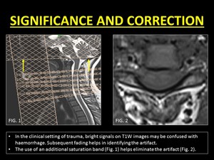
Fig. 11: Correction of Entry Slice Phenomenon.
References: Department of Radiology, SevenHills Hospital, India
Clinical Significance:
ESP is seen commonly on T1W images.
The hyperintense signal imparted on the initial images can be easily confused with subarachnoid haemorrhage.
Reduced hyperintensity in subsequent slices is a good indicator of the signal being artefactual.
In our institute,
MRIs of the cervical spine images include gradient echo images which not only help reduced artifacts due to shorter TR but also help in identifying blood products (7).
iV.
INTRAVOXEL DEPHASING
The application of gradients causes protons to accelerate or decelerate,
based on the direction of flow,
with a gain or loss in phase respectively.
Within each voxel,
a mixture of stationary and flowing protons may exist causing a difference of phase between the protons (out-of-phase), leading to a reduction of the total signal emitted.
This phenomenon is known as Intravoxel dephasing (ID) (4).
In turbulent flow states,
the magnitude of the ID increases.
In clinical practice,
ID is commonly encountered during imaging of the thoracic spine within the dorsal subarachnoid space.
It is assumed that the turbulence in this region is caused due to a combination of the pulsatile and cranially directed CSF flow along with turbulence created due to the ventrodorsal direction of the CSF flow within the subarachnoid space (1).
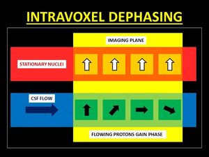
Fig. 12: Following the application of gradients, mobile protons may gain or lose phase. Within a voxel, a mixture of stationary and flowing causes differences of phase between the protons, thus resulting in a reduction of the signal intensity, known as Intravoxel Dephasing.
References: Dr. Vivek Pai
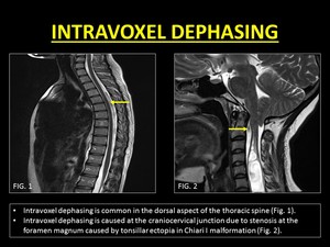
Fig. 13: Demonstration of Intravoxel Dephasing.
References: Department of Radiology, SevenHills Hospital, India
Remedies:
ID can be eliminated by reducing the size of the voxels.
This reduces the chances of co-existence of the out-of-phase protons in the same voxel (1).
Use of gradient echo sequence is another method to rectify artifacts due to ID.
The short TE and rephasing pulse effectively eliminates ID (4).
Clinical significance:
1.Vascular Flow voids: ID is a commonly misinterpreted as vascular flow voids which are associated with dural arterio-venous fistulae and hemangioblastomas (8).
It must be remembered that vascular flow voids are continuous,
curvilinear serpiginous structures which cannot be eliminated with smaller voxel imaging.
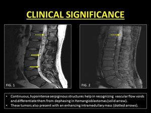
Fig. 14: Vascular flow voids within the CSF may confuse radiologists. They often mimic Intravoxel Dephasing.
References: Department of Radiology, SevenHills Hospital, India

Fig. 15: Vascular flow voids are commonly associated with Dural Arteriovenous Fistulae.
2.Pseudomeningocoeles: ID can help in identifying communication between fluid collections with CSF space.
This is most useful in the evaluation of pseudomeningocoeles.
By definition pseudomeningocoeles occur due to a dural or arachnoid tear following surgery or trauma.
This leads to extravasation and loculation of CSF (9).
The presence of a stenotic jet between the collection and the CSF may be present and helps to clinch the diagnosis of a pseudomeningocoeles (10).
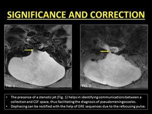
Fig. 16: Clinical use of Intravoxel Dephasing and its correction.
References: Department of Radiology, SevenHills Hospital, India
3.Arachnoid cysts,
webs,
and cord herniations: The other use of ID is in the evaluation of arachnoid cysts.
Arachnoid cysts are intraspinal collections of CSF which may or may not communicate with the subarachnoid space.
However generally CSF contained within the cyst is stagnant or in a very slow state of motion,
not enough to cause dephasing (10).
On the other hand,
in patients with arachnoid webs and ventral spinal herniation,
the absence of a loculated collection and the presence of free-flowing turbulent CSF along the spinal cord gives rise to ID,
thus aiding in differentiating these entities from arachnoid cysts (12).
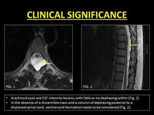
Fig. 17: Role of Intravoxel Dephasing in differentiating arachnoid cysts from cord herniations.
References: Dr. Kanchan Gupta and Dr. Bela Purohit.
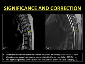
Fig. 18: Intravoxel dephasing helps in distinguishing arachnoid cysts from webs. Correction of the artifact can be achieved with the help of imaging using smaller voxel sizes.
References: Department of Radiology, SevenHills Hospital, India


 signal loss. In order to generate a signal, protons must receive both 90° and 180° pulses. Thus mobile protons which move out of the imaging slice between the 2 pulses are unable to generate signal.
References: Dr. Vivek Pai")


