The dynamic ultrasonography of the shoulder is performed with varying degrees of patient arm rotation and joint stress maneuvers.
Proper use of the ultrasound transducer,
a high-frequency (9-15 MHz) linear array,
is crucial for adequate resolution and visualization.
This technique is useful in the assessment of a wide variety of disorders.
When starting the evaluation,
it is important to collect a short clinical history which can provide clues for the diagnosis.
The shoulder examination may follow different strategies; however,
it is important to follow a standard protocol in order to ensure a global evaluation of the joint.
The proposed standard procedure is divided in 7 steps:
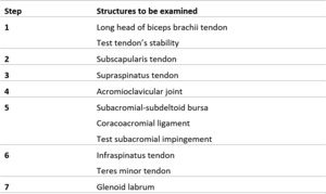
Table 1: Standard ultrasonography procedure: steps with structures to be examined.
The main objectives in each step are:
- Identification of the relevant tendon in two planes (short axis and long axis);
- Elimination of artifacts,
directing the ultrasound beam perpendicular to the tendon;
- Diagnosis.
1- LONG HEAD OF BICEPS BRACHII TENDON
Anatomy:
The long head of biceps brachii tendon (LHBBT) originates mostly from the supraglenoid tuberosity of the scapula and partly from the superior labrum as a long and cylindrical tendon,
which passes within the joint superiorly and obliquely under the rotator cuff,
between the supraspinatus tendon and the subscapularis tendon through the “rotator interval”.
The LHBBT is secured within the bicipital groove by the “transverse humeral ligament”,
which passes between the greater and lesser tuberosities over the sheath of the tendon.
The LHBBT is covered by a synovial sheath that communicates with the joint capsule.
Procedure:
- Patient position: Arm in neutral position with hand resting on thigh with palm up and elbow flexed to 90º.
- Scanning and normal findings: Place the transducer anteriorly in a horizontal position and find the bicipital groove (between the lesser and greater tuberosities of the humerus).
Within the bicipital groove,
the LHBBT can be seen in the short axis.
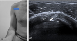
Fig. 1: Long head of the biceps brachii tendon (short axis). (a) Transducer placement. (b) Corresponding US image shows LHBBT (arrow) in the bicipital groove. D= deltoid muscle; GT= greater tuberosity; LT = lesser tuberosity.
Next,
the probe must slide distally to evaluate the vertical part of the LHBBT up to the myotendinous junction,
located under the humeral insertion of the pectoralis major tendon.
In order to evaluate the LHBBT tendon in the long axis,
the probe must be turned 90° clockwise,
the tendon appearing as a fibrillar and hyperechoic structure.
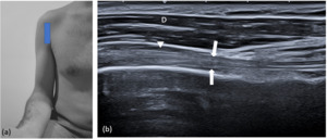
Fig. 2: Long head of the biceps brachii tendon (long axis). (a) Transducer placement. (b) Corresponding US image shows LHBBT (arrows) in long axis. D = deltoid muscle; Arrow head= subacromial-subdeltoid bursa.
- Supplementary: Test tendon’s stability during external rotation of the arm,
which accentuates the subluxation/dislocation of the tendon.
Findings of instability: Partial displacement of the biceps tendon from the bicipital groove is termed subluxation,
and complete medial displacement is termed dislocation.
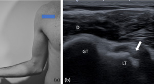
Fig. 3: Test tendon’s stability. (a) Transducer placement with shoulder externally rotated. (b) Corresponding US image shows dislocation of LHBBT (arrow) with complete medial displacement. D= deltoid muscle; GT= greater tuberosity; LT = lesser tuberosity.
- Check: Normal thickness,
echogenicity,
laminated echotexture,
course,
lack of fluid or synovial thickening of tendon sheath and no subluxation or dislocation.
2- SUBSCAPULARIS TENDON
Anatomy:
The subscapularis is the largest muscle of the rotator cuff,
with a triangular shape that fills the subscapular fossa,
from which it originates.
Most fibers are directed upwards and laterally,
run under the coracoid,
anterior to the glenohumeral joint,
and insert on the humeral lesser tuberosity.
Procedure:
- Patient position: Arm in external rotation with the elbow flexed at 90º.
- Scanning and normal findings: The probe is again placed over the anterior shoulder in axial plane,
centered over the lesser tuberosity of the humerus,
where the flat tendon of the subscapularis is inserted.
Thus,
it is possible to check the subscapularis tendon in its long axis,
running anteriorly to the lesser tuberosity and posteriorly to the deltoid muscle.
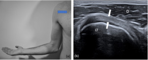
Fig. 4: Subscapularis tendon (long axis). (a) Transducer placement with shoulder externally rotated. (b) Corresponding US image shows subscapularis tendon (arrows) in long axis. D= deltoid muscle; LT = lesser tuberosity.
The transducer is then moved cranially and caudally to ensure complete evaluation.
Special care is needed when evaluating the cranial aspects,
since most tears/tendinopathy involve those areas.
To evaluate on the short axis,
turn the probe 90° clockwise.
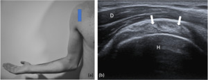
Fig. 5: Subscapularis tendon (short axis). (a) Transducer placement with shoulder externally rotated. (b) Corresponding US image shows subscapularis tendon (arrows) in short axis. D= deltoid muscle; H = humeral head.
- Check: Normal course,
thickness,
attachment,
echogenicity and echotexture.
3- SUPRASPINATUS TENDON
Anatomy:
The supraspinatus muscle sits on the superior area of the scapula,
originates from the supraspinatus fossa and from the homonymous fascia.
Its bundles are directed laterally,
run behind the clavicle lateral edge,
behind the acromion and the coracoacromial ligament,
inserting on the superior border of the humeral greater tuberosity,
where it has a triangular configuration.
Procedure:
- Patient position: Arm in internal rotation with palm of the hand placed over the posterior iliac crest (or “hand in back pocket”).
- Scanning and normal findings: The probe must be placed over the anterior shoulder (superior facet of the greater tuberosity) in an oblique axial plane perpendicular to the course of humeral shaft, to visualize the short axis of the supraspinatus tendon.
The tendon should be a fibrillary pattern and parallel to the curved contour of the humeral head flattening out as it inserts into the greater tuberosity.
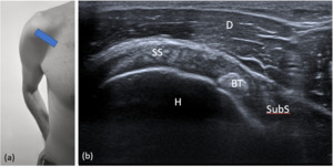
Fig. 6: Supraspinatus tendon (short axis). (a) Transducer placement. (b) Corresponding US image. SS= supraspinatus tendon; BT= biceps brachii tendon; SubS= subscapularis tendon; D= deltoid muscle; H= humeral head.
Long axis of supraspinatus tendon is obtained by rotation of the probe in 90°,
so it is parallel to the course of the humeral shaft.
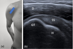
Fig. 7: Supraspinatus tendon (long axis). (a) Transducer placement. (b) Corresponding US image. SS= supraspinatus tendon; D= deltoid muscle; GT= greater tuberosity; H= humeral head.
Since the most tears occur on the most distal portions,
it is important to take special care when evaluating these structures.
- Check: Normal course,
attachment,
thickness,
echogenicity,
echotexture and absence of calcifications.
Smooth superior facet of greater tuberosity.
4- ACROMIOCLAVICULAR JOINT
Anatomy:
The acromioclavicular joint is formed by an articulation between the lateral end of the clavicle and the acromion of the scapula.
It is a flat,
gliding joint that gives the shoulder additional flexibility which would not be possible with the glenohumeral joint alone.
Procedure:
- Patient position: either position.
- Scanning and normal findings: The probe is placed in coronal or slightly oblique coronal plane over the acromioclavicular joint (palpate the clavicle and move laterally toward the acromion),
easily identified by the characteristic bone contours.
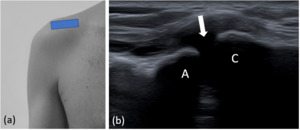
Fig. 8: Acromioclavicular joint. (a) Transducer placement. (b) Corresponding US image shows acromioclavicular joint (arrow). C= clavicle ; A= acromion.
- Check: bone irregularity,
narrowing,
widening or offset.
5- SUBACROMIAL-SUBDELTOID BURSA AND CORACOACROMIAL LIGAMENT
Anatomy:
The subacromial-subdeltoid (SASD) bursa is primarily located below the coracoacromial arch and over the supraspinatus and extends to the greater tuberosity of the humerus.
It can also extend anteriorly over the bicep brachii long head and subscapularis tendons and posteriorly over the infraspinatus tendon.
The coracoacromial ligament is the ligamentous compound of the coracoacromial arch.
It is a strong fibrous triangular band that forms part of the roof of the glenohumeral joint.
It extends from the edge of the acromion,
anterior to the articular surface of the acromioclavicular joint,
to the lateral border of the coracoid process.
Procedure:
- Patient position: Arm in neutral position.
- Scanning and normal findings: The SASD bursa is identified by placing the transducer along the long axis of the humerus,
lateral to the greater tuberosity.
Thus,
the SASD bursa appears as a thin uniform 1–2-mm hypoechoic bursal line between hyperechoic peribursal fat.
Fig. 2: Long head of the biceps brachii tendon (long axis). (a) Transducer placement. (b) Corresponding US image shows LHBBT (arrows) in long axis. D = deltoid muscle; Arrow head= subacromial-subdeltoid bursa.
The probe is placed in axial plane to visualize anterior part of acromion.
Medial side of the probe is moved downwards to visualize coracoid process,
while the lateral side is still kept on acromion.
Coracoacromial ligament is a thin,
fibrillar,
hyperechoic structure passing in between these two bony landmarks,
and supraspinatus muscle is coursing just beneath it.
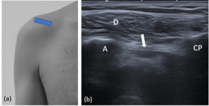
Fig. 9: Coracoacromial ligament . (a) Transducer placement. (b) Corresponding US image shows coracoacromial ligament (arrow). A= acromion; CP= coracoid process; D= deltoid muscle.
- Supplementary - Test subacromial impingement:
The transducer is moved laterally from the acromioclavicular joint to visualize antero-lateral part of acromion and the greater tuberosity of humerus in the same view,
with the supraspinatus tendon between them.
This dynamic evaluation can be executed with the patient abducting his arm with a flexed elbow or via passive arm elevation by the examiner,
to control patient movement.
During this movements the supraspinatus tendon and overlying SASD bursa should slide smoothly under the acromion and out of view.
Findings of impingement: Pooling of bursal fluid at the lateral acromion edge; interposition of the supraspinatus tendon between the greater tuberosity and the acromion; direct contact between the greater tuberosity and the acromion.
- Check: SASD bursa and ligament not thickened.
No subacromial impingement.
6- INFRASPINATUS AND TERES MINOR TENDONS
Anatomy:
The infraspinatus muscle originates from the infraspinatous fossa of the scapula,
runs laterally and inserts on the middle facet of the greater tubercle of the humerus.
The teres minor muscle originates on the superior part of the lateral border of the scapula,
just below the insertion in the infraspinatus muscle.
It runs laterally and inserts on the inferior facet of the greater tubercle of the humerus.
Procedure:
- Patient position: arm in neutral position or with palm of the hand on the opposite shoulder,
across their chest.
- Scanning and normal findings: The probe is placed on the posterior face of the shoulder,
just below the scapular spine in a slightly obliquely axial plane,
parallel with the scapular spine.
This position will produce a long-axis view of the infraspinatus tendon,
which is assessed at its insertion on the posterior aspect of the greater tuberosity,
typically with beak-shaped appearance.
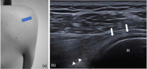
Fig. 10: Infraspinatus tendon (long axis). (a) Transducer placement with arm in neutral position. (b) Corresponding US image shows infraspinatus tendon (arrows) in long axis. Arrow heads= glenoid labrum; H = humeral head.
Moving the probe distally on the humerus,
the teres minor tendon can be seen as a trapezoid structure.Visualization of the teres minor ensures that the entire infraspinatus has been scanned.
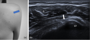
Fig. 11: Teres minor tendon (long axis). (a) Transducer placement with arm in neutral position. (b) Corresponding US image shows teres minor (arrows) in long axis. D= deltoid muscle; GT= greater tuberosity.
To visualize the short axis of infraspinatus and teres minor tendon,
the transducer must be rotated by 90º.
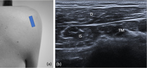
Fig. 12: Infraspinatus and teres minor (short axis). (a)Transducer placement with arm in neutral position. (b) Corresponding US image shows infraspinatus (IS) and teres minor (TM) in the short axis. D= deltoid muscle.
- Check: Normal course,
thickness,
attachment,
echogenicity and echotexture.
7- GLENOID LABRUM
Anatomy:
The glenoid labrum is a fibrocartilaginous structure with ovoid form,
which attaches around the margin of the glenoid cavity and covers the bony surface.
It is essential for the structure and therefore the function of the glenohumeral joint.
Procedure:
- Patient position: arm in neutral position.
- Scanning and normal findings: the transducer is placed in the axial plane over the posterior aspect of gleno-humeral joint. Glenoid labrum is visualized as a hyperechoic triangular structure attached to the bony glenoid rim.
It is important to do a dynamic evaluation with internal and external rotation of the shoulder to check the absence of intraarticular effusion in posterior recess.
Fig. 10: Infraspinatus tendon (long axis). (a) Transducer placement with arm in neutral position. (b) Corresponding US image shows infraspinatus tendon (arrows) in long axis. Arrow heads= glenoid labrum; H = humeral head.
- Check: Normal hyperechoic triangular shape of posterior labrum.
No fluid accumulation in posterior recess.


. (a) Transducer placement. (b) Corresponding US image shows LHBBT (arrow) in the bicipital groove. D= deltoid muscle; GT= greater tuberosity; LT = lesser tuberosity.")
 Transducer placement with shoulder externally rotated. (b) Corresponding US image shows dislocation of LHBBT (arrow) with complete medial displacement. D= deltoid muscle; GT= greater tuberosity; LT = lesser tuberosity.")
. (a) Transducer placement. (b) Corresponding US image shows LHBBT (arrows) in long axis. D = deltoid muscle; Arrow head= subacromial-subdeltoid bursa.")
. (a) Transducer placement with shoulder externally rotated. (b) Corresponding US image shows subscapularis tendon (arrows) in long axis. D= deltoid muscle; LT = lesser tuberosity.")
. (a) Transducer placement with shoulder externally rotated. (b) Corresponding US image shows subscapularis tendon (arrows) in short axis. D= deltoid muscle; H = humeral head.")
. (a) Transducer placement. (b) Corresponding US image. SS= supraspinatus tendon; BT= biceps brachii tendon; SubS= subscapularis tendon; D= deltoid muscle; H= humeral head.")
. (a) Transducer placement. (b) Corresponding US image. SS= supraspinatus tendon; D= deltoid muscle; GT= greater tuberosity; H= humeral head.")
 Transducer placement. (b) Corresponding US image shows acromioclavicular joint (arrow). C= clavicle ; A= acromion.")
 Transducer placement. (b) Corresponding US image shows coracoacromial ligament (arrow). A= acromion; CP= coracoid process; D= deltoid muscle.")
. (a) Transducer placement with arm in neutral position. (b) Corresponding US image shows infraspinatus tendon (arrows) in long axis. Arrow heads= glenoid labrum; H = humeral head.")
. (a) Transducer placement with arm in neutral position. (b) Corresponding US image shows teres minor (arrows) in long axis. D= deltoid muscle; GT= greater tuberosity.")
. (a)Transducer placement with arm in neutral position. (b) Corresponding US image shows infraspinatus (IS) and teres minor (TM) in the short axis. D= deltoid muscle.")