ECR 2020 / C-05682

Advanced cardiovascular computed tomography (CT) imaging in children with congenital heart disease: from volume rendering (VR) to 3D models and 3D printing.
Congress:
ECR 2020
Poster Number:
C-05682
Type:
Educational Exhibit
Keywords:
Performed at one institution, Not applicable, Congenital, Computer Applications-3D, Image manipulation / Reconstruction, CT-Angiography, CT, Paediatric, Cardiovascular system, Cardiac
Authors:
F. Zuccarino1, A. Perez1, M. C. Escobar-Diaz1, A. Valls1, I. Barber2, J. M. Caffarena1, S. Congiu1, J. Sanchez de Toledo1, J. Munuera1; 1Barcelona/ES, 2Esplugues de Llobregat (Barcelona)/ES
DOI:
10.26044/ecr2020/C-05682
 in newborn with aortic coarctation realized without sedation and in free breathing.
MPR and VR reconstructions shows morphology of ascending aorta (AA), aortic arch (ARCH), the location of stenosis (preductal), the patent ductus arteriosum and absence of other collaterals.
References: Hospital Sant Joan de Deu, Barcelona")
Fig. 4:
CT of Coarctation :
Low dose CT (0,4 msV) in newborn with aortic coarctation...

Fig. 5:
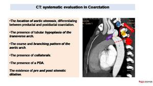
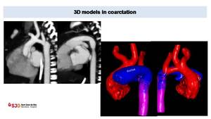
CT: systematic evaluation in Coarctation
. MPR images (images on the left) shows a large vascular structure probably corresponding to a ductus arteriosum.
3D model (images on the right) depicts better than MPR or VR images the anatomy of the aortic arch (in red), the course of carotid and subclavian arteries and the presence of a large ductus arteriosum (in blue). All these information are key for a correct surgical planning.
References: Hospital Sant Joan de Deu, Barcelona")
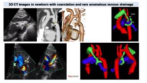
Fig. 6:
Preductal coarctation in newborn, low dose CT (0,3 mSV). MPR images (images on...
 and the presence of an anomalous vessel (white arrow). CT with MPR and VR reconstructions better shows pre and post stenotic dilation of the aorta (arrows). 3D model depicts an anomalous drainage (vessel in green) of the left superior pulmonary vein (LSPV), with a rare course surrounding ipsilateral pulmonary artery.
References: Hospital Sant Joan de Deu, Barcelona")
Fig. 7:
Coarctation in newborn. Echocardiography shows preductal coarctation (*) and...
 confirm the absence of re-stenosis.
References: Hospital Sant Joan de Deu, Barcelona")
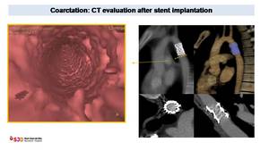
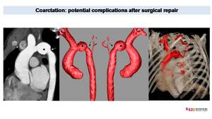
Fig. 8:
Coarctation treated with stent implantation. MPR and VR images depict a...
 in the transverse aortic arch and a moderate re-stenosis in the isthmus (arrows). Both are rare but potential complications after surgical repair.
References: Hospital Sant Joan de Deu, Barcelona")
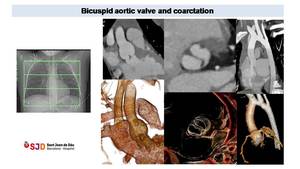
Fig. 9:
Control in twelve years old patient with bicuspid aortic valve and coarctation...

Fig. 10:
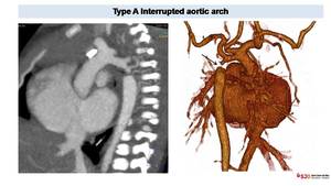
Anomalies in the aortic arch morphology after surgical repair. CT can...
 better define in VR reconstructions. The interruption is located after left subclavian artery ostium, representing a type A in the Celoria-Patton classification.
References: Hospital Sant Joan de Deu, Barcelona")
Fig. 11:
Interrupted aortic arch in newborn with cyanosis. CT easily depicts the...
 of a tortuous aortic arch at the level of the ligamentum arteriosum (yellow line) suggestive of pseudocoarctation . We can also appreciate atherosclerotic plaques but no aortic collaterals.")
Fig. 12:
CT in adult patient shows kinking (arrows) of a tortuous aortic arch at the...
 in two years patient with dysphagia. CT oblique image shows ARSA the compress moderately the esophagus (*). VR images demonstrate the retroesophagic course of ARSA without tracheal stenosis.
References: Hospital Sant Joan de Deu, Barcelona")
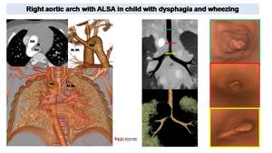
Fig. 13:
Left aortic arch with an aberrant right subclavian artery (ARSA) in two years...
 shows a right aortic arch (RA) and a retroesophagic left subclavian artery (ALSA) with proximal dilation corresponding to Kommerell diveticulum (KD). VR and MinIP reconstructions demonstrate tracheal stenosis due to aortic and ALSA compression. Virtual endoscopic images (on the right) depict luminal tracheal stenosis above the carina.
References: Hospital Sant Joan de Deu, Barcelona")
Fig. 14:
Vascular ring in child with dysphagia and wheezing.
Low dose CT (0,3 mSV)...
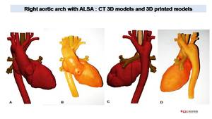
 for analysis of complex cardiac or vascular anatomy. 3D models can be printed (B,D) for pre-surgical evaluation or to evaluate potential use of cardiac and vascular devices.
References: Hospital Sant Joan de Deu, Barcelona")
Fig. 15:
Same patient with ALSA than figure 14
CT allows generate accurate 3D models...
, that passes the midline posterior to the esophagus (yellow arrow). VR sagittal images evidence no tracheal stenosis (airways in pink). 3d model demonstrates the posterior course of the aortic arch (Arch) and its relationship with the esophagus (in green). We can also appreciate a posterior left subclavian artery (LSA) and a left descending aorta (DA).
References: Hospital Sant Joan de Deu, Barcelona")
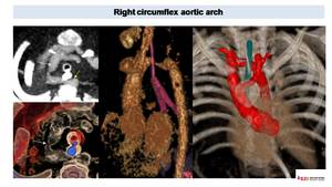
Fig. 16:
Right circumflex aortic arch.
Axial CT images defines a right aortic arch...
.
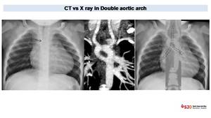
Chest X ray shows a stenosis of distal portion of the trachea (arrow). Aortic arch in not well visualized and descending aorta is medialized. CT with coronal reconstructions confirm the presence of a double aortic arch generating a complete vascular ring with two symmetric aortic arches that encircle the trachea and the esophagus as shown in the superposition of CT and X ray con the right.
References: Hospital Sant Joan de Deu, Barcelona")
Fig. 17:
Double aortic arch in one year old patient with TOF and a Complete...
.
VR images better define the double aortic arch generating tracheal (T)and esophagic stenosis (E) and proximal esophagic dilation (yellow arrow). Cardiac chamber can also be studied and CAVC, right ventricle stenosis (S) and interventricular communication (IVC) can be define (no as better than in echocardiography because is not a cardiac gated study).
References: Hospital Sant Joan de Deu, Barcelona")
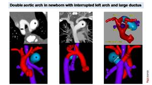
Fig. 18:
Double aortic arch in one year old patient with TOF and a Complete...
 shows double aortic arch with dominant right arch (RA). 3D model images demonstrate four artery sign and an interrupted left aortic arch (arrow) with the presence of a big ductus (D) contributing to trachea (T) and esophagic stenosis. LA: left arch. LSA: left subclavian artery, RSA right subclavian artery, LC: left carotid artery, RC right carotid artery.
References: Hospital Sant Joan de Deu, Barcelona")
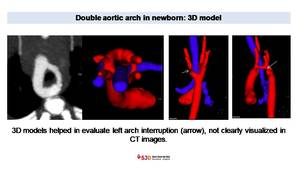
Fig. 19:
Suspected Double aortic arch in newborn.
Low dose CT (0,3 mSV) shows double...
, not visualized in CT image on the left. References: Hospital Sant Joan de Deu, Barcelona")
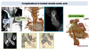
Fig. 20:
3D model in patient with double aortic arch helped in diagnose left arch...
. Aorto-aortic bypass was realized. Later stenosis of the proximal portion of this bypass was also treated with intraluminal stent (green circle). Successive CT control show stent severe stenosis (green images, arrows).
References: Hospital Sant Joan de Deu, Barcelona")
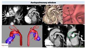
Fig. 21:
Complicated DAA in ten years old patient.
Right arch, treated with stent...
 and ascending aorta (AA) (Black arrows) corresponding to aortoplmonary window. VR and endoscopic images shows vessel distribution at this level. 3D models helps in the evaluation of vessel anatomy and in the pre surgical planning. Post surgical image depict absence of communication between aortic and pulmonary lumen (green circle).
References: Hospital Sant Joan de Deu, Barcelona")
Fig. 23:
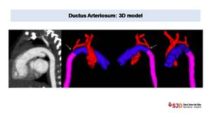
CT in two years old patient with TOF.
We can appreciate a communication...
, the presence of a large ductus connecting pulmonary artery (blue) with descending aorta (pink).
References: Hospital Sant Joan de Deu, Barcelona")
Fig. 24:
Large ductus arteriosum in newborn with severe aortic coarctation. 3D models...
 showing small patent ductus (arrows) incidentally diagnosed in an adult. Right images (C;D) demonstrate a small ductus diverticulum, not connected with pulmonary artery and with calcified wall (arrows).")
Fig. 25:
Sagittal oblique CT images and VR (A;B) showing small patent ductus (arrows)...
 and a Gore-Tex conduct connecting RV and PA. Echocardiography showed a probable stenosis. CT angiography and 3D model of pulmonary arteries confirmed a kinking (arrow) in the proximal portion of the conduct and a small right pulmonary artery with proximal stenosis. On the axial image on the right we can see good CT visualization of pulmonary artery in patient with TOF and pulmonary stenosis treated with intravascular stents References: Hospital Sant Joan de Deu, Barcelona")
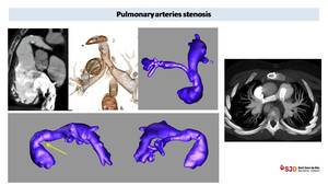
Fig. 26:
PA Stenosis in 8 years old child with previous Truncus arteriosum Type II...
 demonstrates the absence of communication between pulmonary artery en right ventricle (arrow).VR reconstructions shows systemic collaterals that support pulmonary flow.
References: Hospital Sant Joan de Deu, Barcelona")
Fig. 27:
Pulmonary atresia in seven months patient with TGA. Low dose CT (0,4 mSv)...
 thoracic AngioCT (sedation, 6 ml of i.v. contrast and 5 ml of saline solution at 1ml/s). CT shows thoracic aorta (AA) originating from right ventricle (RV) and right aortic arch. Descending aorta (DA) is located on the right. Pulmonary arteries are absent (circle) and lung arterial supply is granted from large collateral arteries (MAPCAs) originating from the aorta and subcalvian arteries. 3D model helps to understand the complex cardiac and vascular anatomy and to visualize MAPCAS (in pink) before eventual endovascular catheterism. Even more, we can better appreciate the tracheal compression (arrows) in correspondence of the origin of the brachiocephalic trunk.
References: Hospital Sant Joan de Deu, Barcelona")
Fig. 28:
Newborn with dyspnea and agenesis of pulmonary artery. Low dose (0,3 mSV)...
. We can also appreciate a diffuse aortic hypoplasia (AH) and a pulmonary artery dilation (PAD).
References: Hospital Sant Joan de Deu, Barcelona")
Fig. 22:
Four years old children with Williams Syndrome. CT sagittal and volumetric...
 or Fontan procedure (yellow arrows) and asses Glenn permeability. Late CT acquisition can be necessary to rule out Fontan thrombosis.
References: Hospital Sant Joan de Deu, Barcelona")
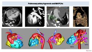
Fig. 29:
CT can define postsurgical changes after Glenn (green arrows) or Fontan...
 is dilated and originates above a VSD as an overriding aorta. VR images define better the anatomy of pulmonary arteries and the presence of MAPCAs originating from thoracic aorta. 3D model better show the anatomy and course of these collaterals (painted in pink, yellow, orange and green) and their relationship with aorta (in red), trachea (in brown) and pulmonary arteries (in blue).
References: Hospital Sant Joan de Deu, Barcelona")
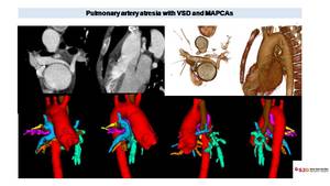
Fig. 30:
CT in ten years old patient with PA with VSD. Axial image shows two small...
 with scimitar morphology. VR demonstrate systemic supply of a portion of right lower lobe (white arrow) separated from the rest of pulmonary parenchyma by a fissure suggestive of sequestration (black arrow).
References: Hospital Sant Joan de Deu, Barcelona")
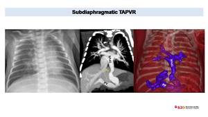
Fig. 31:
PAPVR with scimitar syndrome and sequestration in four years old children. CT...
. We can appreciate diaphragmatic stenois of pulmonary vein (arrow).
References: Hospital Sant Joan de Deu, Barcelona")
Fig. 32:
TAPVR in newborn with congestive pulmonary edema. Chest x ray shows enlarges...
 and VSD (blue arrow). Lobar pulmonary artery are enlarged causing compression over airways (arrow) and mosaic pulmonary pattern. VR images shows the complex anatomy with right aortic arch (RAA), enlarged right ventricle and outflow tract (RVOT) as pulmonary arteries.
References: Radiology, Hospital Sant Joan de Deu, Barcelona")
Fig. 33:
Control in patient with TOF. We can appreciate typical overriding aorta (OA)...
 depict diffuse air trapping, predominant in right lung. 3D model images define the clear compression of the right main bronchi (arrows) due to severe right pulmonary artery enlargement.
References: Radiology, Hospital Sant Joan de Deu, Barcelona")
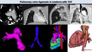
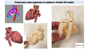
Fig. 34:
Pulmonary valve agenesis in TOF. CT image shows dilated pulmonary arteries. MPR...
 and decide surgical treatment or decide what kind of pulmonary prosthesis is better to use.
References: Hospital Sant Joan de Deu, Barcelona")
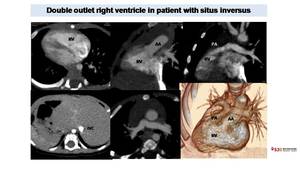
Fig. 35:
3D printed model obtained from 3D model created with CT images. We can...
. Axial images shows dextrocardia with a right apex. Abdominal images demonstrate situs inversus with liver and inferior vena cava (IVC) on the left, spleen on the right. MPR images shows how both thoracic aorta and pulmonary artery origin from right ventricular cavity. VR images better demonstrate the DORV and the spatial relationship between vessels and heart cavities.
References: Radiology, Hospital Sant Joan de Deu, Barcelona")
Fig. 36:
CT in patient with Double outlet right ventricle (DORV). Axial images shows...
 that originates form left ventricle (LV). Pulmonary artery is in anterior position (after Lecompte procedure). CT allows define pulmonary artery morphology that present proximal stenosis of main pulmonary arteries and distal dilation. VR gives a cohmprensive evaluation of the anatomy. We can also see pulmonary bronchiectasis.
References: Radiology, Hospital Sant Joan de Deu, Barcelona")
Fig. 37:
CT in two years old child with TGA surgically corrected with arterial switch....
 in the medium basal interventricular septum, that is not akinetic/diskinetic and presents myocardial systolic thickening, suggestive of cardiac diverticulum.
References: Radiology, Hospital Sant Joan de Deu, Barcelona")
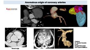
Fig. 38:
Patient with aortic mechanical prosthesis. Cardiac CT retrospectively gated...
 from left sinus with an intramural course (yellow arrow). With CT is possible to detect anomalous origin from pulmonary artery as in the images on the right (Courtesy Dr. Amador Gonzalez Eva R Hospital Universitrio Son Espases Mallorca)
, with an origin of the left coronary artery (LCA) from the pulmonary artery (PA) defined ALCAPA References: Hospital Sant Joan de Deu, Barcelona and Hospital Universitrio Son Espases, Mallorca")
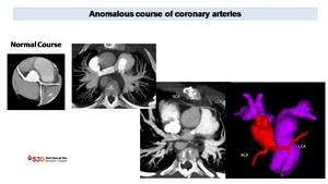
Fig. 39:
Cardiac CT in patient with supraortic stenosis. CT, thanks to VR...
 LCA course, anterior to pulmonary artery in violet), important to determine before possible new surgical treatment, to avoid iatrogenic lesions.
References: Radiology, Hospital Sant Joan de Deu, Barcelona")
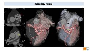
Fig. 40:
Anomalous origin and course of LCA in patient with TOF. CT was realized without...
 into pulmonary artery (PA) representing a coronary fistula to PA. VR images better shows the complex anatomy of the coronary fistula (white circle) and its relationship with surrounding structures.")
Fig. 41:
Cardiac CT in adult patient with coronary fistula. Axial images shows an...

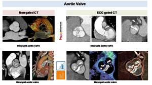
Fig. 42:
CT can define BAV morphology both in non gated than in gated ECG CT scan....

Fig. 43:
Seven years old patient with bicuspid aortic valve and aortic coarctation...
. MPR images and Diastolic and systolic VR reconstruction shows thickened leaflets with good opening but incomplete closure.
References: Radiology, Hospital Sant Joan de Deu, Barcelona")
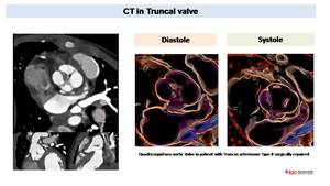
Fig. 44:
Retrospectively gated cardiac CT in infant with truncus arteriosum Type II...

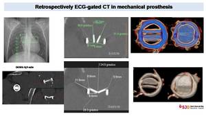
Fig. 45:
CT in mechanical prosthesis. Retrospectively ECG-gated CT realized without i.v....
. We can easily define an incorrect position due to early displacement of a self-expanding pulmonary valve on the right, where the prosthetic pulmonary valve is displaced into the right ventricular outflow tract, parallel to pulmonary artery long axis and its diameter is enlarged (43 mm vs the normal value of 32 mm)
References: Radiology, Hospital Sant Joan de Deu, Barcelona")
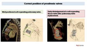
Fig. 46:
CT evaluation of correct and incorrect prosthesis position. VR images easily...
 and thrombus (other images) can be detected with ECG-gated CT scan with i.v contrast.
References: Radiology, Hospital Sant Joan de Deu, Barcelona and Radiology Hospital del Mar")
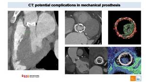
Fig. 47:
Potential complications of mechanical prosthesis. Paravalvular leak (image on...
 draining into the left atrium (LA). This rare condition represents a right to left shunt and may lead to embolic infections, generally cerebral abscess.
References: Radiology, Hospital Sant Joan de Deu, Barcelona")
Fig. 48:
15 years old boy with history of Cor Triatriatum Sinister, surgical repaired...