THE HARDWARE ITSELF
Bones – or joints – kept fixated for some time will eventually consolidate into either arthrodesis or fracture healing.
Hardware provides temporary support by stabilizing and diverging forces from the area.
Hardware is not adequate for long term stability - when consolidation or arthrodesis does not occur,
with time,
any material will eventually fail – like a paper clip being bent multiple times.
When consolidation does occur,
most hardware is no longer necessary,
and is left in place (unless it causes symptoms).
Articular replacements also have their limitations and limited lifespan,
having been developed and used in order to provide better functional performance than the patients own diseased joint.
Many complications may be radiologically assessed.
APROACHING AN IMAGING STUDY
Paying attention to the clinical information and communication with the attending physician is,
as always,
beneficial as many procedures and clinical doubts are specific to the context.
When assessing an radiograph,
the “rules of two” are always a wise starting point.
- two views
- two joints (above and below the injury)
- two sides (for comparison)
- two occasions (may need a follow up x-ray)
Orthopedic hardware has in most instances two reasons for being used
- As articular -or bone - prosthesis
- Fixation devices as in fracture healing
Articular prosthesis are designed to provide movement to diseased joints.
The most common are knee and hip prosthesis.
However,
many other joints may be submitted do arthroplasties for different pathologies - degenerative,
inflamatory or neoplastic processes.
(Fig. 1 / Fig. 2 / Fig. 3 / Fig. 4)
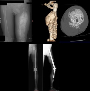
Fig. 3: Patient with an extensive osteosarcoma of the left thigh. Digital topogram (top, left) 3D reconstruction (top, middle) and axial CT (top right) show a aggressive looking lesion with osteoid matrix. Bottom shows AP and lateral radiograph 1 year follow-up post-op finding where a whole femoral replacement placed with a total knee prosthesis.
When hardware is used as fixation devices,
what the referring physicians is hoping to see is the fixation and healing.
(Fig. 8)
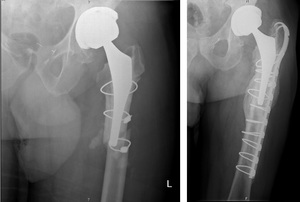
Fig. 8: Left hip radiograph shows an oblique fracture in the proximal femur diaphysis. On the right, it is possible to see a bone callus with bone remodelling. A hook plate with cerclage wires were used to reduce the fracture.
The hardware itself may fracture (Fig. 5 / Fig. 6 ),
disengage (Fig. 7) or loosen (Fig. 9).
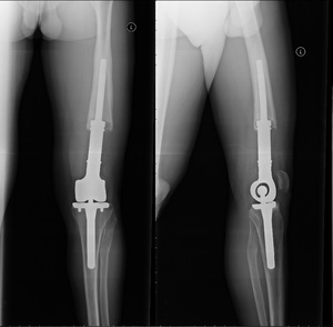
Fig. 9: 22 year old male, previously submitted to a knee resection due to sarcoma. A fully constrained knee prosthesis with an extended femoral component is seen. The femoral component shows bone resoption in a windshield wiper pattern, with regular contours, indicating a mechanical loosening
Differences in the stress distribution after fixation predispose to fractures.
( Fig. 8).
Fig. 8: Left hip radiograph shows an oblique fracture in the proximal femur diaphysis. On the right, it is possible to see a bone callus with bone remodelling. A hook plate with cerclage wires were used to reduce the fracture.
It is may be difficult to differentiate on imaging alone infection from loosening.
A windishield wiper,
or pistoning lucent areas may sugest an mechanical cause.
Periosteal reaction or wider lytic areas may be a finding sugestive of infectious ethiology of the orthopedica material.
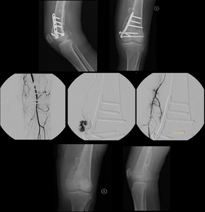
Fig. 10: (TOP) Patient with distal femoral fracture submitted to open reduction with internal fixation with skin incision infection. Note the screw loosening. (MIDDLE) Due to hemorrhage in the superior lateral genicular artery, the patient was submitted to angiography with supraselective embolization of microspheres
(DOWN) Six months after surgical removal of the bone graft material, note the extensive and thick periosteal reaction on the medial aspect of the knee.
Other complications are rather material-specific: silicone synovitis,
asymmetric wear in polyethylene prosthesis,
metallosis with metal-metal prosthesis.
FIXATION DEVICES
The goal of most instrumentation is to provide proper immobilization and compression.
Failure to do so will make it impossible to have adequate bone healing.
It requires that a “bridge” redirects the force away from the diseased bone .
Fixation devices can be classified into internal or external fixation devices.
INTERNAL FIXATION DEVICES
- Screws
- Plates
- Wires and pins
- Intramedullary rods and nails
- Spinal fixation device
EXTERNAL FIXATION DEVICES
- Fracture fixation
- Bone lenghthning
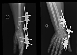
Fig. 48: AP and lateral wrist radiograph. Distal extremity of the radius fracture, treated with external fixation (pins placed in the proximal radius and the second metacarpal) and a single k-wire placed from the radial tuberosity crossing the fracture line.
Screws are one of the most versatile and ubiquous orthopedic material found. (Fig. 11)
Screws may be divided into static screws (Fig. 13) or dynamic screws (Fig. 12)
Different designs also affect their their function or usual use:
Plates are used not only for stabilization,
but may also be used for compression or to work as a buttress (counter-force).
- Dynamic compression plate compression is provided by eccentric placement of screws that,
when tightened,
draw both ends closer together (Fig. 17)
-
Reconstruction plates (Fig. 18) are often used for pelvic or calcaneal fractures as they are maleable and able to be molded to irregular bone surfaces
-
Neutralization plates (Fig. 19) aredesigned for protecting surface fractures from axial loading,
bending and rotation. Acts as protection device by allowing the primary fracture fixation to be accomplished with other devices such as lag screws.
-
Butress plates (Fig. 20) are used to rigidly hold in place fractures at the end of long bones,
especially at the knee and ankle,
where the fracture site experiences compressive and other distorting forces.
The broad end and the adequate contour at the end of the platemakes it more suitable.
-
Hook plate (Fig. 21) are sometimes used to treat acromioclavicular dislocation.
Dynamic hip screws (DHS) are a type of hardware which was specifically designed for treating hip fractures and is currently a current favourite for treating kind of fracturesas it provides resistance to bending while allowing progressive impactation along the lag screw. Used primarily for intertrochanteric fracture,
well vascularized zones of the hip because using it for a more proximal bone might lead to bone ischemia and osteonecrosis.
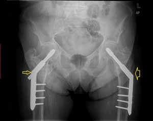
Fig. 22: Pelvis AP radiograph shows bilateral Dynamic hip screws (DHS). There is telescoping on the right (slim arrow) related to impacting of the fracture along the mechanical axis of the hip. On the left (fat arrow), there is no discernible telescoping of the lag screw.
For the most proximal fractures,
instead of the DHS,
the parallell screws will cause less trauma to an area with fewer blood supply.
If perfectly parallel,
the bone will impact just like with an DHS.
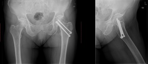
Fig. 23: AP and false profile incidence of the left hip. Three canulated lag screws were applied to treat a subcapital hip fracture. This patient’s left leg had been previously amputated below the knew (not shown)
Girdlestone procedure - Pain is generated by the synovium nerves from the articular capsule being painful.
Removing the femoral head and neck is effective alleviating the pain which is considered by patients an satisfatory results.
The leg is shortened at about 3-10 cm.
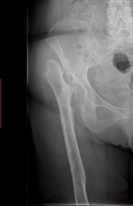
Fig. 25: AP radiograph of the hip. On the right side, there is complete absence of the femoral head and neck. The great trochanter “articulates” with the lateral ilium. This is the typical appearance of a Girdlestone procedure.
WIRES
Wires are another versatile modality of orthopaedic hardware.
Cerclage wires are usually placed in circunference to the bone in order to secure the bone fragments closer together.
( Fig. 24 )
Tension band wiring is a techniche which allows the conversion of disctractive forces into compressive forces.
Common aplications are patellar and olecraneum fractures.
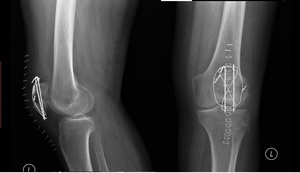
Fig. 26: AP knee radiograph and lateral knee radiograph. There is a transverse patellar fracture treated with Kirschner wires and with tension band wiring. These transform distraction forces into compressive forces
KIRSCHNER WIRES (K-wires) are used for guiding canulated wires,
help stabelize and reduce fractures.
They are very versatile and minimally invasive. K-wires can be safelly placed across physeal plates and across articular surfaces.
RODS AND NAILS
Intramedullary devices marked a great advance in fracture treatment,
allowing earlier weight bearing and less invasive procedures.
Placement of endomedullary devices may require reaming (removal of the medulary contents) as the excessive pressure caused during rod insertion (hammering) might shatter the bone or cause fat embolism.
Compromising endomedulary circulation makes it almost essential that skin overlying the fracture is intact - "adequate skin conditions" - in order to prevent osteonecrosis or osteomyelitis.
Some of these endomedullary devices are composed by long,
slender,
and rather flexible metalic rods,
such as the Ender Nails ( Fig. 27)
Probably the current favourite is the Interlocking Nail.
These combine the use of a nail as well as screws connecting the bone to the nail,
allowing earlier weight bearing,
Further advantages are the possible placement with minimal invasion,
less soft tissue damage,
better blood supply (mainly periosteal).
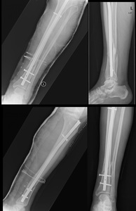
Fig. 28: AP (left top) and lateral (left bottom) tibial shaft radiograph immediately post-op. An intramedullary locking nail was used due to a transverse fracture in the distal tibial shaft. On the right, there’s an AP (bottom) and lateral (top) radiographs 3 months after surgery, showing callus formation.
Concerning sub-trochanteric hip fractures,
these injuries tend to behave mechanically as a femoral fracture.
Sub trochanteric puts substantial stress on the lateral plate.
This led to the development of the special nails such as the Gamma nail.
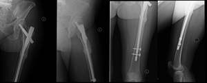
Fig. 29: AP radiograph of the left hip (first from left); false profile (second from left); AP and lateral femoral radiograph (third and fourth from left). Patient treated with an intramedullary locking nail for a subtrocanteric fracture, currently consolidated.
If an arthrodesis is the procedure intended,
nails and rods may be placed crossing the articular surfaces along the mechanicl axis,
providing a solid support for bone consolidation to occur.
Fig. 30: AP pangonogram. Transarticular nail was used for joint arthrodesis. The knee joint line was ressected. The nail is fixated to the tibial and femoral shaft by a screw.
SPINAL FIXATION DEVICES
Trauma,
degenerative diseases and congenital abnormalities are among the most common reasons for spinal intrumentation.
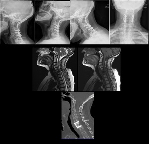
Fig. 31: TOP: Lateral neck view (lateral, extension, flexion) and AP view. Patient previously submitted to surgery with occipital plates due to basilary invagination, posterior luxation of C2. There’s an anterolystesis of C6 (grade II) as well as sclerosis of the vertebral platforms. MIDDLE – T2W and T1W didn’t show evident signs of medullary compromise, even though the patient was symptomatic.
BOTTOM – Sagital reconstruction of CT shows reduction of the lystesis, fixation with plate and screws.
Long-term spinal stability requires fusion between levels.
The purpose of spinal instrumentation is to provide temporary imobilization until the artrodesis is sufficient for mechanical stability.
Anterior or posterior surgical approaches are possible at all levels.
Each level has particularities that may make one or another favourable regarding the specific clinical situation.
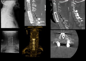
Fig. 32: TOP swimmer’s incidence of the cervical spine and AP incidence of the cervical spine. Posterior instrumentation with was performed with screws in the lateral masses, connected with parallel rods. Anteriorly there’s a plate and fixating C4-D1. There is also a bone graft replacing the vertebral bodies. CT scan sagittal MIP reconstruction (second from left, TOP), sagittal CT reconstruction (third and fourth from left, top) shows detail of bone graft, the positioning of the articular screws and the absence of the posterior arches from C5 to C7.
Spinal fusion may be achieved by using wires,
screws,
rods and plates in order to connect at least two levels.
External fixation devices may also be used,
but usually as a temporary fixation method.
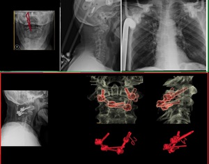
Fig. 33: TOP - Open mouth incidence (left) and lateral cervical spine radiograph show fracture of the base of the odontoid with displacement. An Halo traction vest was placed. There screws attached to the calvaria and to the thoracic skeleton (right). Bottom – Definite Fracture fixation was made by placing screws in the lateral masses of C1 and in the lamina of C2.
Scoliosis led to the development of much of the intrumentation used today.
The Harrington rod was one of the firs methods of spinal intrumentation avaiable.
Because it used distraction forces only on two points,
to achieve reduction in smaller Cobb angles an excessive amount of force had to be used.
The following methods of spinal instrumentation focused on multiple level intrumentation,
with hooks,
with laminar wires and later on with pedicular screws.
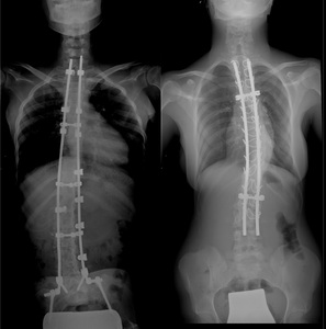
Fig. 34: LEFT – Idiopathic scoliosis treated with posterior instrumentation. The parallel rods extends from the cervical spine to the ilium, where a rod is inserted into the ilum. The rods are interconnected with stabilizing bridge and are fixated t the spine via hooks. RIGHT – Toracic instrumentation. The parallel rods are connected with two stabilizing bridges. The rods are fixated to the vertebral column by laminar wires.
Although diagnosed as a 10º Cobb angle in the coronal plane,
the pathological starting point is a rotation in the vertebral body.
Laminar hooks (with compression and distraction foreces) and wires have a limited control over this rotational component.
This fact was addressed with the use of pedicular screws.
These are currently one of the most widely used (not only for scoliosis) as it allows better control of the vertebral body alignement and correction of its rotation.
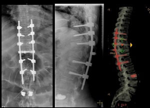
Fig. 35: AP and lateral spine radiograph of the thoracic spine. Compression fracture of D11. Presence of transpedicular screws connected to a rod system. The rod system itself is connected by a bridge at T11. Note the presence of radiodence cement in L3.
Hardware positioning in the spine (particularly pedicular screws) is a delicate procedure and post-op imaging should assess their positioning.
Regarding pedicular screws' positioning,
medially there's the spinal cord; laterally the screw would not provide sufficient purchase and noble structure might be injured.
Caudally and cephalically are the nerve roots,
which might cause severe pain and fuctional compromise.
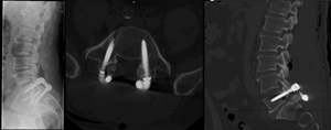
Fig. 36: Patient submitted to surgery due to spondylolisthesis. LEFT: lateral incidence radiograph of the lumbar spine; Center and right – CT with axial and sagittal reconstruction. There are trasn-pedicular screws placed at L5 and S1 levels. The lamina have been removed. There is also marked sclerosis of the intersomatic platforms at L5/S1, as well as a “cage” between the somatic levels.
Other types of material such as titanium boxes,
bone grafts or even prosthesis have also been developed.
COMPLICATIONS OF SPINAL SURGERY
The complications that should be carefully assessed are:
- incorrect level submited to surgery
- hematoma
- infection
- instability
- instrument failure (look for attachment sites,
junctions,
along rigid portion
- stenosis (immediatly above or below the intrumented segments)
- Pseudarthrosis (usually 6-9 months for radiological fusion; 2 years for a fusion to remodel)
ARTHROPLASTY
Hip and knee replacements are one of the most common procedures today.
In 2010,
in the US,
there was an average of 1 surgery per thousand of inhabitants,
and the double of knee replacement surgeries.
In Europe there has been a steady increase in the number of this procedures,
and probably the demographics are rather similar to the US.
HIP REPLACEMENT
Total hip replacement is an invasive procedure.
Other alternatives have been attempted in order to minimize trauma.
Total hip prothesis is used when the femoral head and the acetabulum have both pathological changes.
Hip endoprothesis without acetabular component is used when the femoral head alone is diseased.
Femoral resurfacing are procedures designed to postpone a hip replacement surgery (Fig. 47).
Girdlestone procedure was discusssed above.
It is a last resource surgery being used in most cases for neuropathic or infectious disease.
Complications
1.
Heterotopic bone formation
2.
Loosening
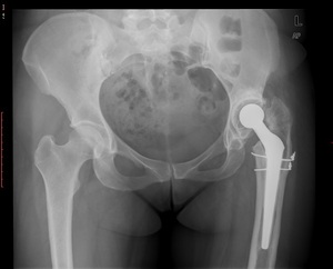
Fig. 46: AP radiograph shows leg shortening and migration of the femoral component. There are also radiolucent zones surrowding the acetabular component.
- Mechanical loosening may appear as pivotting,
pistoning
- Plain radiographs may be sufficient in an adequate clinical setting
- Infection is always a major concern when loosening is present.
Usually presents with a more focal bone resoption,
increased inflamatory markers and more precociously.
- 1 year after the surgery MMA usualy contracts,
which is not considered a true loosening.
- A radiolucent line of 1-2 mm,
non progressive in following radiographs is probably not significant.
- MMA may induce marked progressive osteolysis.
Distinction from infectious ethiology is not always easy.
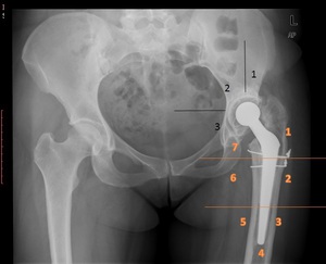
Fig. 37: AP radiograph shows leg shortening, migration of the femoral component with radiolucent lines. There are also radiolucent zones in the acetabular component. Gruen (femoral - orange) and DeChaney (acetabular - black)zones may be used for follow up.
3.
Infection
- Most occur in the first 4 months
- Diagnosis may be difficult and may present with a radiologically normal hip.
Resoption and periosteal reaction may be the only findings.
- Fluroscopic guided hip aspiration (2 weeks after antibiotic discontinuation) with asseptic technique may be performed if inflamatory marker are elevated or if there is an increased suspection index.
Skin flora may confuse results or (worse) be innoculated.
- Arthrograms are not routinely performed in most settings.
They may,
however,
provide important informations regarding the fistulous trajects.
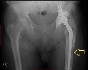
Fig. 38: Patient with several previous total hip prosthesis complicated with infection presented with purulent fistula (yellow arrow)
4.
Fracture,
dislocation
- When identified intraoperativelly,
stabilize with wire
- Dislocation may happen post-operativelly due to lax muscles,
or due to loosening of the prosthesis components.

Fig. 39: Pelvis radiogram shows left hip luxation of the femoral component (left) treated with closed reduction (rigt). There is also bilateral signs of loosening with a windshield wipring pattern.
The acetabular components are rotated.
Normal alignement
- Should be neutral or sligghtly valgus
- Little or no anteversion
- Acetabular component should be 45º with 10º anteversion
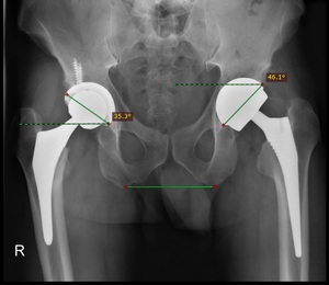
Fig. 40
5.
Metalosis
May occur due to metal wear in metal-metal prothesis.
Besides the expected prothesis wear damage,
dissemination of metal debris to regional lymph nodes has been documented.
The potential development of hypersensitivity reactions,
infections,
and tumors are a concern.
Within the involved joint,
metal debris in the synovial membrane leads to a diagnostic radiographic appearance,
with radiodense material observed at the periphery of the joint. Arthrocentesis documents the presence of thick,
dark gray or black fluid.
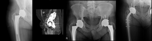
Fig. 45: Patient with pancytopenia of undisclosed origin and presence of total hip prosthesis. There is a dense metal-density area in the right pelvis, also shown in sagittal ct reconstruction (second from right). Metallosis was suspected. The patient was submitted to surgery, where it was confirmed a acetabulum perfortion with wear of the acetabular component. Black fluid was extracted from the pelvis. Revision of the prosthesis was performed (right). The patient recovered from his cell dyscrasia. (Courtesy of Dr. Catarina Oliveira and Dr. Pedro Belo Oliveira)
TOTAL KNEE ARTHROPLASTY
There are several designs avaiable.
Fully constrained prosthesis were the first type of prosthesis available.
Althought they possess intrinsic stability,
they do not reproduce exactly the normal knee rotation and kinematics,
placing an excessive amount of stress in the bone-joint interface,
leading to early loosening.
Fully constrained with rotations are still used in older patients,
with massive tumour resection or in revision arthroplasties.
Fig. 9: 22 year old male, previously submitted to a knee resection due to sarcoma. A fully constrained knee prosthesis with an extended femoral component is seen. The femoral component shows bone resoption in a windshield wiper pattern, with regular contours, indicating a mechanical loosening
More commonly used are the unconstrained models which allow triplanar motion (flexion,
rotation,
distraction).
These have no ligament stability,
meaning the joint stability is provided by sparing the patients own ligaments.
As little bone is actually ressected,
they are composed by "resurfacing" components - both a tibial and a femoral one. Some may also possess a patelar resurfacing component.
Unicompartmental replacements have the advantage of preserving near normal bone stock,
but are less frequently used.
PREOPERTIVE ASSESSMENT
Usually the radiographic assessment should be done with an anteroposterior and lateral knee incidence,
a axial patelar radiograph,
a whole leg length radiograph.
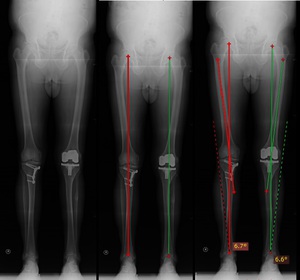
Fig. 41: (LEFT) Patient with buttress place on the right tibia due to previous tibial valgus osteotomy surgery for lower limb alignement. Note the total knee arthroplasty of the left knee (CENTER) Lower limb mechanical axis placed along the center of the knee (between the femoral condyles) (RIGHT) Anatomical axis is drawn along femoral shaft. Angulation with the mechanical axis should be about 7º
Angulation with the femoral mechanical axis is important as this is the best intraopertory reference aviable.
POST-OPERATIVE ASSESSMENT
Follow-up uses both clinical and radiological aspects of the knee prosthesis.
In 1989,
the Knee Society introduced the  Total Knee Arthroplasty Radiographic Evaluation and Scoring System to standardize the radiographic parameters to be measured when reporting radiographic outcomes of TKA:
- component alignment
- tibial surface coverage
- radiolucencies
- patellar problem list that includes angle of the prosthesis,
eccentric component placement,
subluxation,
and dislocation
The development of such scoring systems stresses the need for methodical follow up - quantification of radiolucent areas (in milimeters),
the number of lucent areas,
the angular relationships and,
very importantly,
their evolution are important aspects to pay attention.
Component alignement is an important factor to considerate as mal-alignement is a cause for instability,
loosening and failure.
In a knee AP radiograph,
the angle between the femoral anatomical axis and the femoral component should be about 7º valgus (as previously stated),
which would represent a match with the mechanical axis.
On lateral view,
the femoral component should be nearly perpendicular with the femoral mechanical axis and no lucent spot should be seen.
The tibial component should be placed perpendicular to the tibial shaft (AP),
centered or slightly posterior to the axis on lateral view.
It should slope posteriorly about 10º.
Overhanging of the tibial component may be symptomatic.
The joint line height is determined by measuring the distance from a line passing through the tibial tubercule (perpendicular to the tibial shaft) to a paralell line passing through the the tibial plateau.
- best results are obtained when joint line is altered 8 mm or less
The patellar height is measured from the joint line to the lower patellar pole.
- best results are obtained when the patellar height is 10-30 mm
Loosening is believed to be caused by a combination of mechanical stress,
malalignement,
osteolysis and poor bone stock.
Criteria for diagnosis are
- Increasing radiolucent lines
- component migration
- cement fractures
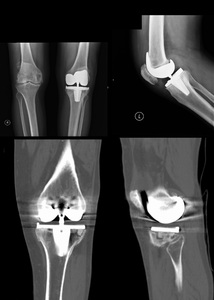
Fig. 42: AP and lateral knee radiograph (top) with CT reformats (bottom). Constrained total knee prosthesis.
There is a tibial subsidence of the medial component with deviation the tibial component. Latrally there is loosening of the tibial component. Note the misalignment of the tibial component with the tibial axis.
Infection is always a consideration with radiolucent lesions,
especially in the first two years.
More commonly they are indolent with mild to moderate disconfort.
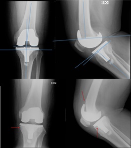
Fig. 43: Left knee AP and lateral radiographs 2 months post-op (TOP) and 9 months post-op (BOTTOM). Immediately post-op there is normal relation between the orthopaedic material and the bones. 9 months after, there are radiolucent line underneath the tibial plateau and the posteriorly to the femoral component (red arrow). This patient was submitted to revision arthroplasty due to septic loosening
Fluoroscopic dynamic examination may be helpful in patients with unexplained pain after TKA and normal radiographs.
Arthrogram with aspiration of knee fluid for culture may also be used.
Contrast medium should not be present in fluid aspiration.
In case of dry tap,
sterile saline lavage has been described.
Presence of contrast in periprothesis is diagnosis of loosening.
Extensor mechanism complications account for probably half the causes for dissatisfaction. Radiographs are instrumental in their diagnosis
Patellar tilt and patellar subluxation are common findings that may imply a tight lateral retinaculum,
a component malrotation or valgus allignment of the extensor mechanism.
Patella alta (due to extensor mechanism rupture) or patella infera (fibrosis in the Hoffa pad) may also be seen.
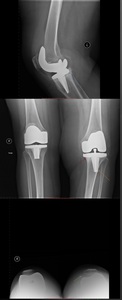
Fig. 44: Bilateral AP radiograph (middle) , left lateral knee radiograph (top) and axial patellar incidence (bottom).
There is a tibial subsidence beneath the medial component, with loosening (red arrow), which dents the lateral cortical surface of the tibia (orange arrow)with a valgus deviation. On the axial view, the patelar tilt (green arrow)

 relative to the anterior body of the talus. CENTER – Replacement of talar dome with articular prosthesis. RIGHT – there is anterior migration and lossening of the talar component of the fracture, which caused signigicant pain")

 3D reconstruction (top, middle) and axial CT (top right) show a aggressive looking lesion with osteoid matrix. Bottom shows AP and lateral radiograph 1 year follow-up post-op finding where a whole femoral replacement placed with a total knee prosthesis.")

RIGHT – patient with secerelly displaced humeral head fracture (top). There is no glenoid damage. A hemiarthroplasty was performed (bottom).")

 and a single k-wire placed from the radial tuberosity crossing the fracture line.")
 and there is a smooth bone resorption in a windshield wiper patern, compatible with loosening")


")


. Bottom-right shows the formation of bone callus with radiological consolidation.")

. There is telescoping on the right (slim arrow) related to impacting of the fracture along the mechanical axis of the hip. On the left (fat arrow), there is no discernible telescoping of the lag screw.")
")


 there’s a radiolucent line in the cortical bone (blue arrow) in as well as an increase in the density of the cortical bone. Femoral AP radiograph (right) shows a fracture in the ender nail. This patient had had surgery many years ago.")
; false profile (second from left); AP and lateral femoral radiograph (third and fourth from left). Patient treated with an intramedullary locking nail for a subtrocanteric fracture, currently consolidated.")
 and lateral (left bottom) tibial shaft radiograph immediately post-op. An intramedullary locking nail was used due to a transverse fracture in the distal tibial shaft. On the right, there’s an AP (bottom) and lateral (top) radiographs 3 months after surgery, showing callus formation.")


 and lateral cervical spine radiograph show fracture of the base of the odontoid with displacement. An Halo traction vest was placed. There screws attached to the calvaria and to the thoracic skeleton (right). Bottom – Definite Fracture fixation was made by placing screws in the lateral masses of C1 and in the lamina of C2.")
 and AP view. Patient previously submitted to surgery with occipital plates due to basilary invagination, posterior luxation of C2. There’s an anterolystesis of C6 (grade II) as well as sclerosis of the vertebral platforms. MIDDLE – T2W and T1W didn’t show evident signs of medullary compromise, even though the patient was symptomatic.
BOTTOM – Sagital reconstruction of CT shows reduction of the lystesis, fixation with plate and screws.")

, sagittal CT reconstruction (third and fourth from left, top) shows detail of bone graft, the positioning of the articular screws and the absence of the posterior arches from C5 to C7.")


, allowing some degree of impaction to occur in the weight bearing axis. On the right, bone callus is already formed (red arrow)")
 Front knee radiograph shows a not recent inter-condylar fracture which extended laterally. The condyles were fixated using lag screws (only the distal portion acquires purchase). (Right) Lateral cervical radiograph. A canulated wire is placed from the axis body to the odontoid tip. A not recent fracture is seen at the odontoid base.")
 radiograph shows sclerosis and joint space narrowing between the lunate and capitate. There is also proximal capitate migration into the space created by the scapholunate dissociation. The third and fourth from the left show an scaphoid excision with a four corner fusion achieved by using Herbert screws to fixate the carpal bones")