Injuries to the dental hard tissues and the pulp
1.
Infraction: An incomplete fracture (crack) of the enamel without loss of tooth structure.
Imaging techniques: Periapical radiograph,
unless other symptoms are present.
Imaging features: No radiographic abnormalities are present but a fracture line on the surface of the tooth is visible clinically.
2.
Enamel fracture: A fracture confined to the enamel with loss of tooth structure (Fig.
2).
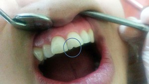
Fig. 2: Enamel fracture on the incisal edge of the left maxillary incisor tooth.
Imaging techniques: Periapical radiographs at different horizontal angles to rule out the possible presence of a root fracture or a luxation injury.
Imaging features: The enamel loss is visible on the radiographs.
3.
Enamel-dentin fracture (uncomplicated enamel and dentine facture): A fracture confined to enamel and coronal dentin with loss of tooth structure,
but without pulpal exposure.
Imaging techniques: Periapical radiographs at different horizontal angles to rule out the possible presence of a root fracture or a luxation injury.
In case of lip or cheek lacerations,
radiographs are indicated to search for tooth fragments or foreign material.
Imaging features: The enamel-dentin loss is visible.
4.
Enamel-dentin-pulp fracture (complicated enamel and dentine facture): A fracture involving enamel and coronal dentin with loss of tooth structure and pulpal exposure.
Imaging techniques: Periapical and occlusal radiographs.
Periapical radiographs at different horizontal angles to rule out the possible presence of a root fracture or a luxation injury.
In case of lip or cheek lacerations,
radiographs are indicated to search for tooth fragments or foreign material.
For moderate and severe trauma,
CBCT is also recommended for diagnosis and treatment planning.
Imaging features: The loss of tooth substance is visible.
5.
Crown-root fracture: A fracture involving enamel,
dentin and cementum with loss of tooth structure.
The pulp may or may not be exposed.
Imaging techniques: Periapical and occlusal radiographs.
Periapical radiographs at different horizontal angles,
in order to detect fracture lines in the root.
CBCT imaging can reveal the extent of the fracture.
Imaging features: Apical extension of fracture may not always be visible on periapical radiographs.
6.
Root fracture: A fracture confined to the root of the tooth involving cementum,
dentin,
and the pulp.
As the apical segment is usually not displaced,
root fractures can be further classified by whether the coronal fragment is displaced (see luxation injuries) or not.
These fractures can also be classified by level in coronal,
middle-root,
and apical (Fig.
3).
Another type of classification can be made based on the direction of the fracture in vertical (Fig.
4),
horizontal,
and oblique planes.
The vertical root fracture is defined as a longitudinally oriented fracture that originates from the root canal wall in the apical part of the root and extends coronally and toward the outer surface of the root.
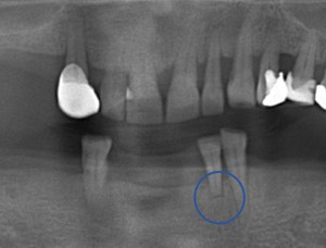
Fig. 3: Cropped panoramic radiograph demonstrates horizontal apical root fracture of the left mandibular lateral tooth.
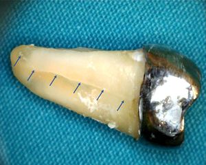
Fig. 4: Extracted right mandibular second molar tooth with vertical root fracture (arrows).
Imaging techniques: Periapical and occlusal radiographs,
CBCT.
Periapical radiographs at different horizontal angles,
in order to detect fracture lines in the root.
The ability of a radiographic image to reveal the presence of a root fracture depends on the relative angulation of the incident x-ray beam to the fracture plane and the degree of separation of the fragments.
On the other hand,
several small field of view CBCT systems can resolve 150 μm or less,
and such high-resolution,
small field of view (FOV) CBCT imaging may be of great value in the detection of tooth fractures.
The diagnosis of vertical root fractures is complicated as direct visualization of the fracture line may not be possible clinically and radiographically,
besides the lack of specific signs and symptoms.
Various clinical and imaging methods such as apex locators,
laser,
optical coherence tomography,
tuned aperture computed tomography,
conventional computed tomography and CBCT were used to detect vertical root fractures.
Among these,
the latter is gaining acceptance as a useful imaging method for the diagnosis of these fractures,
although with varying sensitivity and specificity.
Imaging features: The fracture involves the root of the tooth and is in a horizontal,
diagonal or vertical plane.
If the x-ray beam is aligned along the fracture plane,
a single sharply defined radiolucent line can be seen on conventional radiographs.
However,
if the orientation of the x-ray beam meets the fracture plane obliquely,
the fracture plane may appear as a more poorly defined single line or as two lines that converge at the mesial and distal surfaces of the root.
The appearance of a comminuted root fracture may also be less well defined.
In some instances,
the only evidence of a fracture may be a localized increase in the width of the periodontal ligament space adjacent to the fracture site.
CBCT imaging can reveal the extent of the fracture as x-ray orientation is not a limitation for this technique.
However,
because of image artifact from root canal filling material and metal posts and lack of separation of fracture fragments,
detection of root fractures on CBCT is still a challenge (Fig.
5).
Figure 6-8 shows radiographic and CBCT images of a patient with two fractured teeth.
The images in cross-sectional and sagittal planes reveal the orientation,
extent and number of fractures in detail.
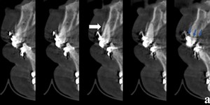
Fig. 5: Sagittal CBCT sections showing alveolar fracture (white arrow) and radiolucent artefact from metal brackets simulating a crown fracture (blue arrows) (The images in this presentation were obtained using a Planmeca Promax 3D Mid, Helsinki, Finland, 2011; the exposure parameters were 10 mA 90 kVp, 13-27 s.; voxel size was 400 µm).
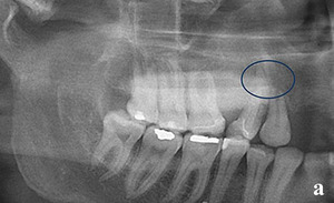
Fig. 6: Cropped panoramic radiograph shows root fractures of the right maxillary canine and first premolar teeth.
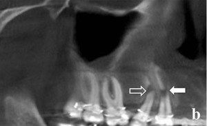
Fig. 7: Pseudopanoramic view of CBCT image shows apical oblique displaced root fracture of the right maxillary first premolar and middle-root horizontal displaced root fracture of the right maxillary canine tooth.
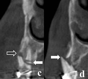
Fig. 8: Cross-sectional CBCT images. Oblique middle-root fracture and labial displacement of the buccal root (hollow arrow) and two coronal horizontal fractures of the palatal root of the right maxillary first premolar (white arrow) (left). Lateral luxation of the right maxillary canine tooth with displacement of the root through the labial alveolar bone accompanied by vertical root fracture (white arrow) (right).
Injuries to the periodontal tissues
1.
Concussion: An injury to the tooth-supporting structures without increased mobility or displacement of the tooth,
but causing inflammatory edema.
Imaging techniques: Periapical radiographs at different horizontal angles to rule out the possible presence of a root fracture or a luxation injury.
Imaging features: No radiographic abnormalities,
or slight widening of the periodontal ligament space.
2.
Subluxation: An injury to the tooth supporting structures resulting in increased mobility,
but without clinical or radiographic displacement of the tooth.
Imaging techniques: Occlusal,
orthogonal periapical,
and periapical radiographs at different horizontal angles.
Imaging features: Usually no radiographic abnormalities.
3.
Extrusion: Partial displacement of the tooth out of its socket.
Imaging techniques: Occlusal,
orthogonal periapical,
and periapical radiographs at different horizontal angles.
Imaging features: Widened periapical ligament space (see Fig.
10).
4.
Lateral luxation: Displacement of the tooth other than axially.
Displacement is accompanied by comminution or fracture of either the labial or the palatal/lingual alveolar bone.
Imaging techniques: Occlusal,
standard periapical,
and periapical radiographs at different horizontal angles of the tooth in question.
Imaging features: Widened periapical ligament space.
5.
Intrusion (intrusive luxation): Displacement of the tooth into the alveolar bone.
This injury is accompanied by comminution or fracture of the alveolar socket (Fig.
9).
Imaging techniques: Occlusal and periapical radiographs.
If the tooth is totally intruded a lateral exposure is indicated to make sure the tooth has not penetrated the nasal cavity.
Imaging features: The periodontal ligament space may be absent from all or part of the root.
The cemento-enamel junction is located more apically in the intruded tooth than in adjacent non-injured teeth,
at times even apical to the marginal bone level (Fig.
10).
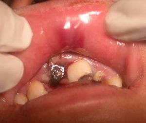
Fig. 9: Intraoral photograph shows bleeding of the gingiva and hematoma of the lip mucosa. Incisal edge of the right maxillary central incisor tooth and a crown fracture of the rotated left maxillary central incisor tooth are visible .
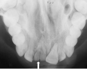
Fig. 10: Occlusal radiograph shows intrusion of the right maxillary central incisor tooth into the alveolar bone and vertical crown fracture (arrow). Extrusion of the left maxillary central incisor tooth is remarkable.
6.
Avulsion: The complete seperation of a tooth from its alveolus by traumatic injury.
Imaging techniques: If the clinical examination raises suspicion of a possible intrusion,
root fracture,
alveolar fracture or jaw fracture,
an occlusal radiograph should be made to confirm the diagnosis.
Imaging features: The empty socket is visible,
and in a recent avulsion,
the lamina dura is apparent.
Injuries to the supporting bone
Alveolar fracture: A fracture of the alveolar process; with or without concomitant involvement of the alveolar socket.
Teeth associated with alveolar fractures are characterized by mobility of the alveolar process.
Imaging techniques: Occlusal and periapical radiographs.
Panoramic or CBCT imaging are also useful (Fig 5 & 11).
Imaging features: The vertical line of the fracture may run along the periodontal ligament space or in the septum.
The horizontal line may be located at any level,
from the marginal bone to the basal bone.
An associated root fracture may be present.
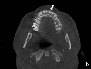
Fig. 11: Axial CBCT image shows labially deplaced cortical plate fracture (arrow).
Traumatic injuries to the facial bones
1.
Mandibular Fractures: Classification of the mandibular fractures to the anatomic region involved: Symphyseal- parasymphyseal,
corpus,
angle and ramus mandible.
Fractures affecting the ramus mandible are subdivided into the coronoid or condylar process fractures (Figure 12-15).
Fractures are classified as to whether they are contained within the dental arc or involve the mandibular angle or the ascending ramus.
The most common fracture sites in the mandibular bone are the condyle,
corpus,
and angle,
followed less frequently by the parasymphyseal region,
ramus,
coronoid process,
and alveolar crest.
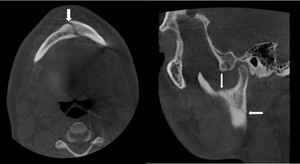
Fig. 12: An axial view of CBCT reveals the fracture in symphyseal region extending to parasymphyseal region (left), a sagittal view of CBCT reveals the fracture line on the ramus between sigmoid notch and posterior aspect of the ramus mandible (right), (arrows).
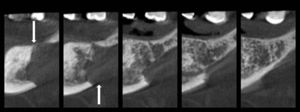
Fig. 13: A mandibular corpus fracture due to plasmacytoma on the edentulous region could be seen on cross-sectional view of CBCT.
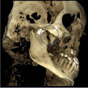
Fig. 14: Three dimensional CBCT reconstruction reveals fracture of coronoid process due to air gun pellet injury.
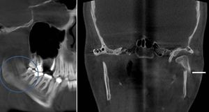
Fig. 15: A pseudopanoramic CBCT image reveals the fracture line in the mandibular angle (left); coronal CBCT section shows a fractured condylar head with displaced fragment (right), (arrows).
Imaging techniques: Panoramic radiography and conventional projection imaging such as occlusal radiographs,
transcranial,
posteroanterior and submentovertex skull views,
lateral oblique views form the baseline for the radiological assessment of patients with suspected mandibular fracture.
However,
conventional projection radiograph is a two-dimensional shadow of a three-dimensional object and these techniques suffer from numerous limitations such as superimposition,
blurring,
and distortion of anatomical structures.
Three dimensional imaging techniques allow visualization of the third dimension while at the same time eliminate superimpositions.
It has been stated that CBCT is superior to panoramic radiography especially at condylar and coronoid fractures and fractures at the anterior part of the mandible which are more difficult to detect due to superimposition.
CBCT data can be reformatted,
and several different types of images in oblique or curved image planes can be synthesized,
in addition to the images in the orthogonal planes and 3D reconstructions (Fig 16).
The slice thickness of the sectional images and slice interval can be defined (Fig 17).
As the number of adjacent voxels included in the display is increased,
the slice thickness of the orthogonal images also increases.
This creates an image slab that represents a specific volume of the patient,
referred to as a ray sum. The resultant image generated from a full-thickness perpendicular ray sum provides a simulated lateral cephalometric image (see Fig.
25-27).
In contrast to conventional radiographs,
these ray sum images are without magnification and distortion.
In addition,
selecting multiple nodes along the centerline corresponding to the jaw arch on an appropriate axial image automatically draws a planning line,
and creates a “simulated” or “pseudopanoramic” image (Fig.
18-22).
Imaging features: Radiographic signs of mandibular fracture include the presence of a radiolucent line,
a change in the normal anatomic outline or shape of the structure,
a defect in the outer cortical boundary and an increase in the density of the bone,
which may be caused by the overlapping of two fragments of bone.
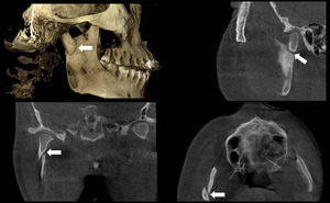
Fig. 16: 3D reconstruction (upper left), sagittal (upper right), coronal (lower left) and axial (lower right) images showing a condylar fracture.
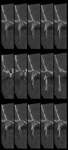
Fig. 17: Cross-sectional images revealing the same condyle fracture. Upper row: The slice thickness is 5 mm, the slice interval is 0,4 mm. The images are somewhat blurred due to the thick sections. Middle row: The slice thickness is 0,4 mm, the slice interval is 5,1 mm. The condyle cannot be viewed in all sections as the slice interval is too much. LOwer row: The slice thickness is 0,4 mm, the slice interval is 0,4 mm. The condyle and the fracture line can be seen in detail.
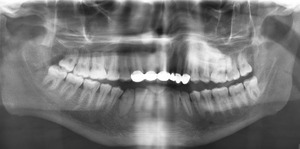
Fig. 18: Symphyseal-parasymphyseal fracture can not be observed in the panoramic radiograph due to the superimposition of cervical vertebrae related to the incorrect patient positioning during radiographic imaging.
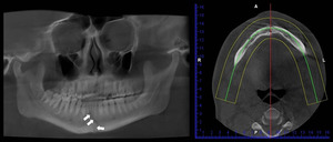
Fig. 19: The figure shows the CBCT images of the case shown in Fig. 18. Symphyseal-parasymphyseal fracture is not clearly seen on the pseudopanoramic CBCT view when the image layer is 25 mm wide, as shown on the axial image on the right.
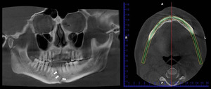
Fig. 20: The figure shows the CBCT images of the case shown in Fig. 18. Symphyseal-parasymphyseal fracture is clearly seen on the pseudopanoramic CBCT view when the image layer is 6 mm wide, as shown in the image on the right.
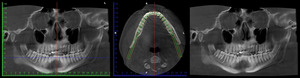
Fig. 21: When the planning line (image in the middle) is drawn at the level of the dental arch (blue line on the image on the left), the fracture line cannot be viewed on the resultant pseudopanoramic view (image on the left).
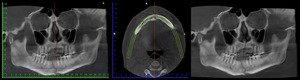
Fig. 22: When the planning line (image in the middle) is drawn at the level of body of the mandible (the blue line on the image on the left), the fracture line is clearly viewed on the resultant pseudopanoramic view (image on the left).
2.
Midfacial Skeleton Fractures: Fractures of the midfacial region may occur at the maxilla alone or may involve other bones,
including the frontal,
nasal,
lacrimal,
zygomatic (Fig 23 & 24),
vomer,
ethmoid,
and sphenoid bones.
Midfacial skeleton fractures were classified by by Leon Le Fort as follows: Le Fort I (horizontal fracture),
Le Fort II (pyramidal fracture),
Le Fort III (craniofacial disjunction) and zygomatic complex fractures.
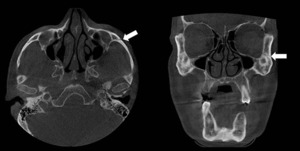
Fig. 23: Fracture of the left zygomatic bone detected at axial and coronal views of CBCT.
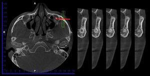
Fig. 24: Cross-sectional images of zygomatic bone were obtained by drawing an image layer vertical to the fracture line.
Le Fort I fracture is a relatively transversal fracture involving the body of the maxilla that results in separation of the alveolar process of the maxilla from the middle face.
The fracture line passes above the teeth,
through the floor of the nose and the maxillary sinuses and tuberosities to the inferior portion of the pterygoid processes (Fig.
25).
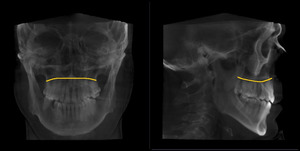
Fig. 25: Representative drawing of Le Fort I fracture on frontal (left) and lateral (right) views that was obtained by cephalometric module from CBCT
Le Fort II fracture has a pyramidal appearance on the posteroanterior skull radiograph.
The teeth are at the pyramid base and nasofrontal suture is at its apex.
The fractures extend laterally through the lacrimal bones and the inferior orbital rims, and inferiorly through the zygomaticomaxillary sutures.
Maxilla is separated from the base of the skull due to the fractures of the nasal bones and frontal processes of the maxilla (Fig.
26).
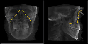
Fig. 26: Representative drawing of Le Fort II fracture on frontal (left) and lateral (right) views that was obtained by cephalometric module from CBCT images.
Le Fort III fracture separates the middle third of the facial skeleton from the cranium.
The fracture line usually extends through the nasal bones and the frontal processes of the maxilla or nasofrontal and maxillofrontal sutures,
across the floors of the orbits,
and through the ethmoid and sphenoid sinuses and the zygomaticofrontal sutures.
It traverses both pterygomaxillary fissures and separates the pterygoid plates where they arise from the sphenoid bone (Fig.
27).
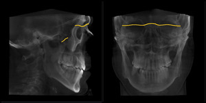
Fig. 27: Representative drawing of Le Fort III fracture on frontal (left) and lateral (right) views that was obtained by cephalometric module from CBCT images.
Imaging techniques: Panoramic radiograph,
occlusal view of the maxilla,
posteroanterior,
Waters',
reverse Towne's,
lateral skull,
and submentovertex projections are the techniques useful for plain film examination of midfacial fractures.
As the complex anatomy of the midface renders the radiographic interpretation of fractures of the midface is difficult,
CT is the modality of choice for imaging.
Large FOV CBCT can also reveal midface fractures without the disadvantage of superimposition.
Magnetic resonance imaging is less sensitive for osseous injury but may have an important role in the evaluation of orbital soft tissue injuries.
Imaging features: Radiographic signs of midfacial skeleton fractures include linear radiolucencies that are usually widest at discontinuities in the cortical margins of bone,
alterations of normal skeletal contour,
displaced fragments of bone,
and separated bony sutures.


.")
 and radiolucent artefact from metal brackets simulating a crown fracture (blue arrows) (The images in this presentation were obtained using a Planmeca Promax 3D Mid, Helsinki, Finland, 2011; the exposure parameters were 10 mA 90 kVp, 13-27 s.; voxel size was 400 µm).")


 and two coronal horizontal fractures of the palatal root of the right maxillary first premolar (white arrow) (left). Lateral luxation of the right maxillary canine tooth with displacement of the root through the labial alveolar bone accompanied by vertical root fracture (white arrow) (right).")

. Extrusion of the left maxillary central incisor tooth is remarkable.")
.")
, a sagittal view of CBCT reveals the fracture line on the ramus between sigmoid notch and posterior aspect of the ramus mandible (right), (arrows).")


; coronal CBCT section shows a fractured condylar head with displaced fragment (right), (arrows).")
, sagittal (upper right), coronal (lower left) and axial (lower right) images showing a condylar fracture.")


 is drawn at the level of the dental arch (blue line on the image on the left), the fracture line cannot be viewed on the resultant pseudopanoramic view (image on the left).")
 is drawn at the level of body of the mandible (the blue line on the image on the left), the fracture line is clearly viewed on the resultant pseudopanoramic view (image on the left).")


 and lateral (right) views that was obtained by cephalometric module from CBCT")
 and lateral (right) views that was obtained by cephalometric module from CBCT images.")
 and lateral (right) views that was obtained by cephalometric module from CBCT images.")