CORONARY COMPUTED TOMOGRAPHY ANGIOGRAPHY
CCTA has been increasingly used in the diagnosis of CAD due to ongoing technical development.
It allow an accurate non-invasive anatomical evaluation of the coronary arteries with highly temporal and spatial resolution.
Patient selection plays an important role in the performance of the exploration.
Indications.6 Table 1
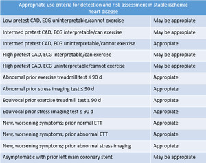
Table 1: Indications. Appropriate use criteria of CCTA for detection and risk assessment on multiple clinical scenarios among with stable ischemic heart disease.6
References: Thomas DM, Branch KR, Cury RC. PROMISE of Coronary CT Angiography: Precise and Accurate Diagnosis and Prognosis in Coronary Artery Disease. South Med J. 2016;109(4):242-7.
Patient preparation:
- Hemodynamically stable
- Slow heart rate (< 65 beats per min).
- To minimize heart rate variability.
- Slow breathing and motionless.
*Pharmacologic intervention: Beta blockers,
sublingual nitroglycerin.
Scanning techniques:
- Prospective ECG-gating,
imaging is performed with single preselected interval after the R wave,
using sequential mode to acquire axial images and an incrementally moving table to cover the heart with minimal overlap of axial slices.
However,
the results will not be achieved if the heart rate increases.
- Retrospective ECG-gating,
imaging is performed throughout the cardiac cycle,
which allows that image reconstruction can take place at any point in the cardiac cycle.
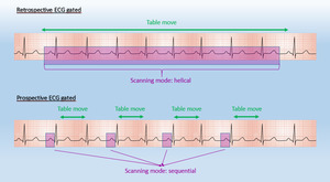
Fig. 1: Diagram about ECG-gated techniques with retrospective ECG-gated (continuous acquisition) and prospective ECG-gated (step and shoot acquisition)
References: Centro de Excelencia de Diagnóstico por Imágenes, Clínica Internacional/Lima-Perú 2018
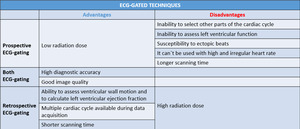
Table 2: Advantages and disadvantages of ECG-gated techniques.
Post-processing techniques:
Maximum-intensity projection (MIP),
displays the voxels of highest attenuation within a volume,
providing an angiography-like image.
It allows a quickly reconstruction of a vascular map.
A disadvantage of MIP is that it can lead to overestimation of coronary stenosis caused by calcified plaque and should never be used to secure a diagnosis without cross-checking thin-section MPR.
Curved multiplanar reformation (curved MPR) display the dataset in any imaging plane of the three-dimensional space.
It allows the depiction of even long and tortuous coronary arteries with a single image.
Volume rendering technique (VRT) is a set of techniques that uses the whole data providing a three-dimensional overview of the anatomy. VRT should not be used to assess coronary stenoses.
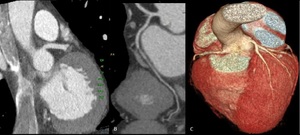
Fig. 2: Post processing imaging techniques. Evaluation of coronary arteries can be performed using common imaging techniques available like maximum-intensity projection(A), curved multiplanar reformation(B) and volume rendering technique(C).
References: Centro de Excelencia de Diagnóstico por Imágenes, Clínica Internacional/Lima-Perú 2018
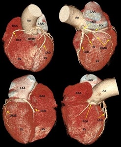
Fig. 3: Three-dimensional volume rendering of the heart. By manual segmentation of the computed tomography images, parts of the right ventricular outflow tract and pulmonary artery have been removed which allows to visualize the entire course of the left main and left anterior descending coronary arteries. (a) View of the anterior face of the heart, (b) View of the left lateral face of the heart, (c) View of the posterior face of the heart and (d) View of the right lateral face of the heart. Ao, aorta; LAA, left atrial appendage; LAD, left anterior descending coronary artery; LCx, left circumflex coronary artery; LMT, left main trunk; LV, left ventricle; OMB, obtuse marginal branch; PDB, posterior descending branch; RAA, right atrial appendage; RCA, right coronary artery; RI, ramus intermedius; RV, right ventricle; RVOT, right ventricular outflow tract.
References: Centro de Excelencia de Diagnóstico por Imágenes, Clínica Internacional/Lima-Perú 2018
NORMAL AND VARIANTS CORONARY ANATOMY
Definition of a coronary artery depends not on its origin and proximal course but on intermediate and distal segments (dependent territory).
Most of the coronary variations may have no clinical significance but knowledge of such anatomical variations is necessary for planning therapeutic interventional procedures.
Normal configuration of coronary arterial tree is variable but typically coronary arteries arise from the ostia of aortic sinuses,
converging towards the apex of the heart.
Coronary ostia can be located below,
at or above the sinotubular junction.
Ostia located just above the aortic sinus are considered variants.7 Ostia located near the aortic valve commissures,
in noncoronary sinus,
or high in the aortic root (1.0 cm above the cusp) are abnormal.
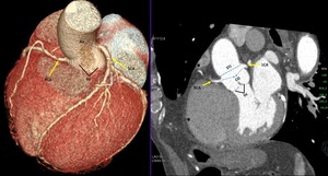
Fig. 4: Coronary ostia. Volume rendering technique and maximum-intensity projection show normal origin of coronary arteries. Ao, Aorta; CO, coronary ostia; LCA, left coronary artery; RCA, right coronary artery; STJ, sinotubular junction; sinus of valsalva.
References: Centro de Excelencia de Diagnóstico por Imágenes, Clínica Internacional/Lima-Perú 2018
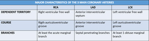
Table 3: Major characteristics of the 3 main coronary arteries. RCA, right coronary artery; LAD, left anterior descending; LCX, left circumflex artery.
Left coronary artery (LCA)
Left main trunk (LMT)
LCA originates from the middle portion of the left anterior sinus of Valsalva,
forming a short,
common left main trunk.
LMT passes between the main pulmonary artery and the left auricle before entering the coronary sulcus.
Reig & Petit classified the LMT as ‘short’ if it is ≤ 5mm and ‘long’ if it is > 15 mm.
It have been identified that short LMT is associated with early atherosclerotic lesions in the anterior descending and circumflex branches,
likely to be related to hydraulic factors.8
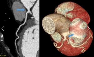
Fig. 5: Short left main trunk (LMT). Curved multiplanar reformation and volume rendering technique show the left main trunk (arrow) is smaller than 5 milimeters.
References: Centro de Excelencia de Diagnóstico por Imágenes, Clínica Internacional/Lima-Perú 2018
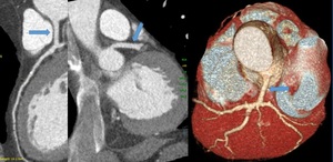
Fig. 6: Long left main trunk (LMT). Curved multiplanar reformation, maximum-intensity projection and volume rendering technique the left main trunk (arrow) is greater than 15 milimeters.
References: Centro de Excelencia de Diagnóstico por Imágenes, Clínica Internacional/Lima-Perú 2018
Occasionally,
LMT is absent,
consequently LAD and CX arises from well-separated coronary ostia at the left aortic sinus,
this has been related with an increased incidence of left coronary dominance.9,
10
Usually,
LMT bifurcates into the LAD and the LCX arteries but sometimes can be divided into three or more branches (38%).11 A third artery so called ramus intermedius artery (RIA).
RIA may behave like a large obtuse marginal (ramus marginalis) or a diagonal branch (ramus diagonalis).
It is also possible to find a left main trunk quadrifurcation and pentafurcation.12
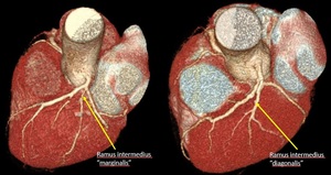
Fig. 7: Ramus intermedius artery. Volume rendering technique.
References: Centro de Excelencia de Diagnóstico por Imágenes, Clínica Internacional/Lima-Perú 2018
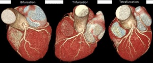
Fig. 8: Branching pattern of left coronary trunk (LCT). Volume rendering technique. Normally, LCT dividing into anterior descending and circumflex arteries (A). Occasionally, LCT presents a trifurcation (B) with intermediate branch, quadrifurcation (C) with double anterior descending artery or two intermediate branches and pentafurcation with three intermediate branches.
References: Centro de Excelencia de Diagnóstico por Imágenes, Clínica Internacional/Lima-Perú 2018
Left anterior descending (LAD)
It arises from the bifurcation of LMT and courses in the anterior interventricular groove,
descending in the epicardial fat obliquely toward the apex of the heart.
Branches:
- Anterior septal perforating branches which supply the anterior 2/3rd of the basal interventricular septum and the entire septum at the mid and apical levels.
- Diagonal branches (1,
2 or 3) that descend diagonally across the anterior surface of the left ventricle.
LAD can be divided:
- Proximal segment: from origin to the origin of first septal perforator.
Sometimes,
the first diagonal branch serves as the boundary between the proximal and middle segment of the LAD
- Middle segment: from the first septal perforator origin halfway to the left ventricular ápex
- Distal segment: from this halfway point to the apex itself.
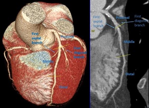
Fig. 9: Segments of left anterior descending. Volume rendering technique and curved multiplanar reformation
References: Centro de Excelencia de Diagnóstico por Imágenes, Clínica Internacional/Lima-Perú 2018
Among all of the coronary arteries,
the left anterior descending artery (LAD) has the most constant course.13 However; the LAD may have some variants like duplications,
short course,
long course of distal segment (recurrent LAD or diaphragmatic) that is associated with short PDB.
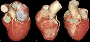
Fig. 10: Variations in the configuration of left anterior descending. Volumen rendering technique. A) Short LAD does not reach the apex of the heart. B) Long course of distal segment of LAD so-called recurrent LAD. C) Tortuose LAD with ‘U’ shaped loop but remains in anterior interventricular groove.
References: Centro de Excelencia de Diagnóstico por Imágenes, Clínica Internacional/Lima-Perú 2018
Dual LAD consists of a short LAD that ends high in the anterior interventricular groove and a long LAD that originates from early branch of the LAD proper or originates from RCA.14 It was first reported and classified into four types by Spindola-Franco et al13 but later have been reported other variants.
The essential criteria to diagnose dual LAD are:
- To identify two LADs.
- One would be large and another small
- Diagonal branches arises from both of them.
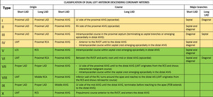
Table 4: Classification of dual left anterior descending coronary arteries based on morphoanatomical features of the coronary arteries including four subtypes described by Spindola-Franco and six additional types described later.
References: Celik T et al. A new anomaly of the left anterior descending artery: Type X dual LAD. Indian Heart J. 2015;67(3):14-17.
Knowledge about dual LAD is essential for adequate surgical planning and revascularization.
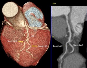
Fig. 11: Dual LAD type 1. Volume rendering technique and curve multiplanar reformation show bifurcation of LAD proper into short LAD and long LAD. Short LAD terminates high in anterior interventricular groove. Long LAD courses in left ventricle parallel to anterior interventricular groove. LAD, left anterior descending.
References: Centro de Excelencia de Diagnóstico por Imágenes, Clínica Internacional/Lima-Perú 2018
Left Circunflex artery (LCX)
Courses toward the left,
along the left auriculoventricular groove,
around the obtuse margin and usually ends before reaching the posterior interventricular sulcus.
LCX has a proximal segment and a distal segment,
divided by the origin of the first obtuse marginal branch.

Fig. 12: Segments of LCX. Volume rendering technique and curve multiplanar reformation show the left circumflex artery in the left auriculoventricular groove. Proximal CX prior to the origin of the first OM. In this case, third OM represents the end branch of the left circumflex coronary artery (distal CX). CX, circumflex artery; OM, obtuse marginal branch.
References: Centro de Excelencia de Diagnóstico por Imágenes, Clínica Internacional/Lima-Perú 2018
Length: 5cm to 8cm.15 Obtuse marginal branches supply the posterolateral aspect of the left ventricle.
Sometimes,
this branches have prominent early branching (high origin) and may be larger than the circumflex coronary artery,
or even represent the end branch of the left circunflex coronary artery.
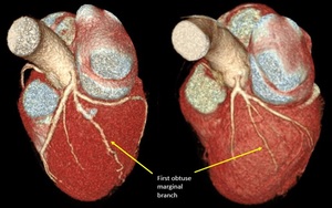
Fig. 13: First obtuse marginal branches of high origin (early branching). Volume rendering technique.
References: Centro de Excelencia de Diagnóstico por Imágenes, Clínica Internacional/Lima-Perú 2018
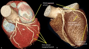
Fig. 14: Variations in configuration of left circumflex artery. Volume rendering technique. A) Long first obtuse marginal with early trifurcation. B) Short distal segment of left circumflex artery which course outside of left auriculoventricular groove and end up as second obtuse marginal branch. LCX, left circumflex artery.
References: Centro de Excelencia de Diagnóstico por Imágenes, Clínica Internacional/Lima-Perú 2018
Right coronary artery (RCA)
Normally,
it originates from the right coronary cusp,
passes anteriorly and to the right,
between the right auricle and the pulmonary artery and then descends vertically in the right atrioventricular groove,
extending to the acute margin of the heart.
The RCA is divided into a:
- Proximal segment: from the origin halfway to the acute margin or to 1st main right marginal branch.
- Middle segment: from this halfway point or 1st main right marginal branch to the acute margin.
- Distal segment: from the acute margin to the base of the heart at the junction of the atrial and ventricular septa (crux of the heart).
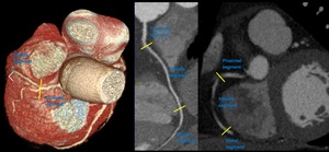
Fig. 15: Segments of right coronary artery. Volume rendering technique, curve multiplanar reformation and maximum-intensity projection.
References: Centro de Excelencia de Diagnóstico por Imágenes, Clínica Internacional/Lima-Perú 2018
It has been observed variations in the course of RCA,
with ‘U’ shaped loop but the clinical implications have not been systematically studied.
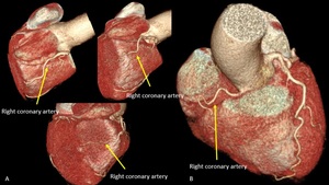
Fig. 16: Variation in the course of RCA. Volume rendering technique. A) Right coronary artery with ‘U’ shaped loop, course outside of right auriculoventricular groove and abnormal position on posterior face of the heart with no visible posterior descending branch. B) Short right coronary artery with ‘U’ shaped loop but course inside of right auriculoventricular groove. In this case, it is a left dominant coronary artery system.
References: Centro de Excelencia de Diagnóstico por Imágenes, Clínica Internacional/Lima-Perú 2018
RCA has highly variable pattern of small branches:
- Conal or infundibular branch: The first branch which supplies the muscular right ventricular outflow tract or infundibulum.
It can be double or multiple.
Sometimes,
conal branch arises separately from the aorta,
very close to the ostium of the right coronary artery (“third coronary”)16.
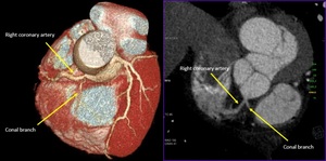
Fig. 17: Conal branch: First branch of right coronary artery. Volume rendering technique and maximum-intensity projection.
References: Centro de Excelencia de Diagnóstico por Imágenes, Clínica Internacional/Lima-Perú 2018
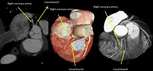
Fig. 18: Maximum-intensity projection and volume rendering technique. “Third coronary”: Variant of Conus branch which arise directly off the right coronary cusp, close to the ostium of the right coronary artery.
References: Centro de Excelencia de Diagnóstico por Imágenes, Clínica Internacional/Lima-Perú 2018
Occasionally,
the conal branch can be a branch of the LCA.
In patients with total occlusion of the LAD or RCA,
the conus artery often serves as a principal source of collateral circulation (circle of Vieussens).
- Sinoatrial nodal branch passes posteriorly around the superior vena cava to supply the sinus node.
In some cases,
it arises from the LCX.
- Right marginal branches supplies the RV free wall.
- Atrioventricular nodal branch.
- Posterior descendent branch (PDB) is the final major branch,
which lies in the posterior interventricular groove.15 Sometimes,
PDB arises from the RCA before the crux of the heart (early branching) or arise of LCX o both (RCA and LCX).
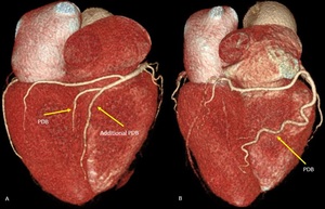
Fig. 19: Early branching of posterior descending branch. Volume rendering technique. A) A posterior descending branch arises from the RCA at the crux of the heart. It is associated with an additional PDB arises before the crux of the heart. B) Very early branching of PDB which travels down the posterior face of right ventricle towards the lower third of the posterior interventricular groove.
References: Centro de Excelencia de Diagnóstico por Imágenes, Clínica Internacional/Lima-Perú 2018
Coronary dominance
Coronary artery dominance is defined by the vessel which gives rise to the PDB and supplies the inferior wall and inferior third of the interventricular septum.
- Right-dominance: 70%,
supply from the RCA
- Left-dominance: 10% supply from the LCX
- Codominance: 20%,
arise from both right and left systems
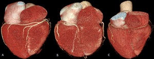
Fig. 20: Coronary arterial dominance. Volume rendering technique. Right dominant (A) with posterior descending artery (PDA) is supplied by right coronary artery (RCA) (80-85%). Left dominant (B), whereby PDA is supplied by left circumflex (LCx) or left anterior descending (LAD) coursing around the apex. Codominant(C) whereby PDA is supplied by branches of both RCA and LAD or LCx.
References: Centro de Excelencia de Diagnóstico por Imágenes, Clínica Internacional/Lima-Perú 2018
Coronary artery segments
Due to the substantial variability of coronary anatomy it is very difficult to establish an adequate segmentation that is sufficiently accurate and practical.
The American College of Cardiology and American Heart Association Guidelines for Invasive Coronary Angiography propose a classification system that consists of 29 segments,
in this nomenclature is considered anatomic variations.17 The Society of Cardiovascular Computed Tomography has been considered a coronary segmentation with 18 segments.
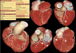
Fig. 21: Volume rendering technique shows coronary segmentation (SCCT) with 18 segments. In red, segments that can be different, in some cases according to coronary arterial dominance.
References: Centro de Excelencia de Diagnóstico por Imágenes, Clínica Internacional/Lima-Perú 2018
Coronary artery anomalies
CAAs are a diverse group of congenital disorders whose manifestations are highly variable.
Although rare,
CAAs may be caused chest pain,
hemodynamically significant abnormalities or even sudden cardiac death.
We can classify them into anomalies of origin,
anomalies of course,
and anomalies of termination (modified classification by Greenberg et al).18,19
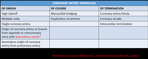
Table 5: Coronary artery anomalies. Modified classification system developed by Greenberg et al.18,19
References: Kim SY et al. Coronary Artery Anomalies: Classification and ECG-gated Multi–Detector Row CT Findings with Angiographic Correlation. RadioGraphics 2006;26:317–334.
Some examples of CAAs:
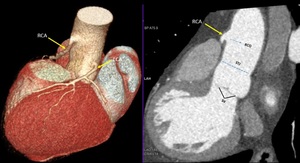
Fig. 22: High takeoff. Volume rendering technique and maximum-intensity projection show the takeoff of the right main coronary artery (yellow arrow) high above the left coronary cusp and sinotubular junction.
References: Centro de Excelencia de Diagnóstico por Imágenes, Clínica Internacional/Lima-Perú 2018
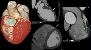
Fig. 23: Myocardial bridging. Volume rendering technique and maximum-intensity projection show long segment of a “tunneled” intramuscular course under a “bridge” of overlying myocardium on middle left anterior descending (yellow arrow). It is noted minimal reduction of luminal diameter. Green arrow: second diagonal branch.
References: Centro de Excelencia de Diagnóstico por Imágenes, Clínica Internacional/Lima-Perú 2018
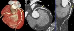
Fig. 24: Coronary aneurism. Volume rendering technique, maximum-intensity projection and curve multiplanar reformation show focal dilation of middle segment on left anterior descending. Coronary aneurism is considered an intrinsic anomaly, it is defined when coronary arterial segments dilates >1.5 times of normal adjacent coronary segments.
References: Centro de Excelencia de Diagnóstico por Imágenes, Clínica Internacional/Lima-Perú 2018
CAD-RADS20
Coronary Artery Disease Reporting and Data System is a tool to report CCTA on patients with suspicion or diagnosed with coronary artery disease.
The aim of these guidelines are to reduce potential ambiguity or missing information,
and to ultimately improve communication of exam findings with patients referring physicians20
Coronary artery interpretation include:
- Systematic review of each coronary segment from multiple planes.
- Awareness of relevant artifacts.
- Evaluation of lesion morphology and composition.
- Assessment of stenosis severity using high resolution images.
CAD RADS categories depends on how severe the coronary stenosis is, and represents the highest-grade coronary artery lesion documented by CCTA.
Maximum diameter stenosis severity can be graded using either a qualitative or semiquantitative stenosis grading system recommended by the Society of Cardiovascular Computed Tomography.
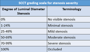
Table 6: SCCT grading scale for stenosis severity.20
References: Cury R et al. SCCT guidelines for the interpretation and reporting of coronary CT angiography: a report of the Society of Cardiovascular Computed Tomography Guidelines Committee. J Cardiovasc Comput Tomogr. 2014;8(5):342-58.
The CAD-RADS classification consists of six grades with CAD RADS 0 (without atherosclerosis) to CAD-RADS 5 (with at least one total occlusion).
CAD-RADS 4 is sub-divided into A and B.
CAD-RADS 4A with Single-vessel or two-vessels demonstrating severe stenosis (70-99%) and CAD-RADS 4B with left main stenosis greater than 50% or three-vessel obstructive disease (>70%).
In the latter case,
it is recommended further evaluation with invasive angiography and possible revascularization.
CAD-RADS 5 is represented by total coronary occlusion which can be acute or chronic.
Its clinical relevance varies widely depending on the clinical context.
In chronic occlusion,
factors such as lesion length,
calcification particularly at the proximal cap,
and degree of collateralization may be of relevance for management decisions.
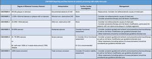
Table 7: CAD-RADS Reporting and Data System for patients presenting with stable chest pain.20
References: Cury R et al. SCCT guidelines for the interpretation and reporting of coronary CT angiography: a report of the Society of Cardiovascular Computed Tomography Guidelines Committee. J Cardiovasc Comput Tomogr. 2014;8(5):342-58.
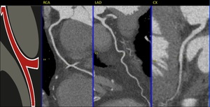
Fig. 25: CAD-RADS 0
References: Centro de Excelencia de Diagnóstico por Imágenes, Clínica Internacional/Lima-Perú 2018
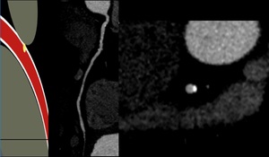
Fig. 26: CAD-RADS 1
References: Centro de Excelencia de Diagnóstico por Imágenes, Clínica Internacional/Lima-Perú 2018
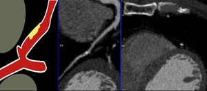
Fig. 27: CAD-RADS 2
References: Centro de Excelencia de Diagnóstico por Imágenes, Clínica Internacional/Lima-Perú 2018
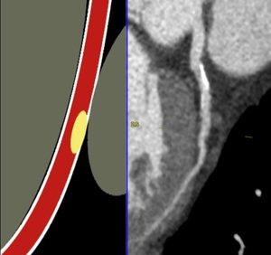
Fig. 28: CAD-RADS 3
References: Centro de Excelencia de Diagnóstico por Imágenes, Clínica Internacional/Lima-Perú 2018
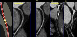
Fig. 29: CAD-RADS 4. In these cases, CAD-RADS A with single-vessel severe stenosis and CAD-RADS 4B with three-vessel obstructive disease (>70%).
References: Centro de Excelencia de Diagnóstico por Imágenes, Clínica Internacional/Lima-Perú 2018
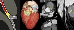
Fig. 30: CAD-RADS 5. Total occlusion (100%) of left anterior descending.
References: Centro de Excelencia de Diagnóstico por Imágenes, Clínica Internacional/Lima-Perú 2018
Modifiers:
A) Study is not fully evaluable or non-diagnostic (N)
If the study is not fully diagnostic (not all segments > 1.5 mm diameter can be interpreted with confidence) and a stenosis with CAD-RADS greater than 3 is present in a diagnostic segment,
should be graded with modifier N for example CAD-RADS 3/N.
However,
for a patient with no stenosis,
minimal or mild stenosis in interpretable segments,
CAD-RADS N should be used due further evaluation to exclude obstructive coronary artery disease is still needed.
B) There are stents (S)
Presence of at least one coronary stent anywhere in the coronary system. If a stent is not evaluable and there is no other stenosis greater than 50% in the coronary tree,
should be classified as CAD-RADS N/S.
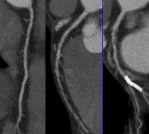
Fig. 31: CAD-RADS S. In this case, the circunflex artery has a coronary stent without re-stenosis and it was found moderate stenosis (60%) then it was classified as CAD-RADS 3/S.
References: Centro de Excelencia de Diagnóstico por Imágenes, Clínica Internacional/Lima-Perú 2018
C) There are coronary bypass grafts (G)
Presence of at least one coronary-artery bypass graft.
A stenosis bypassed by a fully patent graft is not considered for the CAD-RADS classification.
We should always consider the highest-grade coronary artery lesion including stenosis of vein graft.
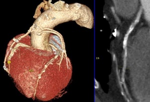
Fig. 32: CAD-RADS G. In this case, the patient has 4 coronary artery bypass grafts with three-vessel obstructive disease (>70%). It was classified as CAD-RADS 4B/G
References: Centro de Excelencia de Diagnóstico por Imágenes, Clínica Internacional/Lima-Perú 2018
D) Vulnerable or High-Risk Plaque Features (V)
Positive remodeling,
low-attenuation plaque (less than 30 HU),
spotty calcification,
and the napkin-ring sign.
With two or more high-risk features,
should be added “V” modifier.
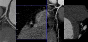
Fig. 33: CAD-RADS V. Atherosclerotic Plaques are particularly susceptible to disruption. In these cases, characteristics of vulnerability are positive remodeling, low-attenuation plaque and spotty calcification
References: Centro de Excelencia de Diagnóstico por Imágenes, Clínica Internacional/Lima-Perú 2018
Use slash (“/”) follow each modifier: N/S/G/V.
Use of CCTA in patients with previously known CAD should be carefully considered due the low positive predictive value.
Especially,
the intermediate lesions that may be overestimated and in stent restenosis (smaller than 3.0 mm diameter).

:242-7.")

 and prospective ECG-gated (step and shoot acquisition) References: Centro de Excelencia de Diagnóstico por Imágenes, Clínica Internacional/Lima-Perú 2018")
, curved multiplanar reformation(B) and volume rendering technique(C). References: Centro de Excelencia de Diagnóstico por Imágenes, Clínica Internacional/Lima-Perú 2018")
 View of the anterior face of the heart, (b) View of the left lateral face of the heart, (c) View of the posterior face of the heart and (d) View of the right lateral face of the heart. Ao, aorta; LAA, left atrial appendage; LAD, left anterior descending coronary artery; LCx, left circumflex coronary artery; LMT, left main trunk; LV, left ventricle; OMB, obtuse marginal branch; PDB, posterior descending branch; RAA, right atrial appendage; RCA, right coronary artery; RI, ramus intermedius; RV, right ventricle; RVOT, right ventricular outflow tract. References: Centro de Excelencia de Diagnóstico por Imágenes, Clínica Internacional/Lima-Perú 2018")


. Curved multiplanar reformation and volume rendering technique show the left main trunk (arrow) is smaller than 5 milimeters. References: Centro de Excelencia de Diagnóstico por Imágenes, Clínica Internacional/Lima-Perú 2018")
. Curved multiplanar reformation, maximum-intensity projection and volume rendering technique the left main trunk (arrow) is greater than 15 milimeters. References: Centro de Excelencia de Diagnóstico por Imágenes, Clínica Internacional/Lima-Perú 2018")

. Volume rendering technique. Normally, LCT dividing into anterior descending and circumflex arteries (A). Occasionally, LCT presents a trifurcation (B) with intermediate branch, quadrifurcation (C) with double anterior descending artery or two intermediate branches and pentafurcation with three intermediate branches. References: Centro de Excelencia de Diagnóstico por Imágenes, Clínica Internacional/Lima-Perú 2018")

 Short LAD does not reach the apex of the heart. B) Long course of distal segment of LAD so-called recurrent LAD. C) Tortuose LAD with ‘U’ shaped loop but remains in anterior interventricular groove. References: Centro de Excelencia de Diagnóstico por Imágenes, Clínica Internacional/Lima-Perú 2018")
:14-17.")

. CX, circumflex artery; OM, obtuse marginal branch. References: Centro de Excelencia de Diagnóstico por Imágenes, Clínica Internacional/Lima-Perú 2018")
. Volume rendering technique. References: Centro de Excelencia de Diagnóstico por Imágenes, Clínica Internacional/Lima-Perú 2018")
 Long first obtuse marginal with early trifurcation. B) Short distal segment of left circumflex artery which course outside of left auriculoventricular groove and end up as second obtuse marginal branch. LCX, left circumflex artery. References: Centro de Excelencia de Diagnóstico por Imágenes, Clínica Internacional/Lima-Perú 2018")

 Right coronary artery with ‘U’ shaped loop, course outside of right auriculoventricular groove and abnormal position on posterior face of the heart with no visible posterior descending branch. B) Short right coronary artery with ‘U’ shaped loop but course inside of right auriculoventricular groove. In this case, it is a left dominant coronary artery system. References: Centro de Excelencia de Diagnóstico por Imágenes, Clínica Internacional/Lima-Perú 2018")


 A posterior descending branch arises from the RCA at the crux of the heart. It is associated with an additional PDB arises before the crux of the heart. B) Very early branching of PDB which travels down the posterior face of right ventricle towards the lower third of the posterior interventricular groove. References: Centro de Excelencia de Diagnóstico por Imágenes, Clínica Internacional/Lima-Perú 2018")
 with posterior descending artery (PDA) is supplied by right coronary artery (RCA) (80-85%). Left dominant (B), whereby PDA is supplied by left circumflex (LCx) or left anterior descending (LAD) coursing around the apex. Codominant(C) whereby PDA is supplied by branches of both RCA and LAD or LCx. References: Centro de Excelencia de Diagnóstico por Imágenes, Clínica Internacional/Lima-Perú 2018")
 with 18 segments. In red, segments that can be different, in some cases according to coronary arterial dominance. References: Centro de Excelencia de Diagnóstico por Imágenes, Clínica Internacional/Lima-Perú 2018")

 high above the left coronary cusp and sinotubular junction. References: Centro de Excelencia de Diagnóstico por Imágenes, Clínica Internacional/Lima-Perú 2018")
. It is noted minimal reduction of luminal diameter. Green arrow: second diagonal branch. References: Centro de Excelencia de Diagnóstico por Imágenes, Clínica Internacional/Lima-Perú 2018")

:342-58.")
:342-58.")


. References: Centro de Excelencia de Diagnóstico por Imágenes, Clínica Internacional/Lima-Perú 2018")
 of left anterior descending. References: Centro de Excelencia de Diagnóstico por Imágenes, Clínica Internacional/Lima-Perú 2018")
 then it was classified as CAD-RADS 3/S. References: Centro de Excelencia de Diagnóstico por Imágenes, Clínica Internacional/Lima-Perú 2018")
. It was classified as CAD-RADS 4B/G References: Centro de Excelencia de Diagnóstico por Imágenes, Clínica Internacional/Lima-Perú 2018")
