ECR 2019 / C-2920
Lateral knee pain: A comprehensive sonographic spectrum of pathologies and guided interventions
Congress:
ECR 2019
Poster Number:
C-2920
Type:
Educational Exhibit
Keywords:
Trauma, Inflammation, Diagnostic procedure, Ultrasound, Musculoskeletal system, Interventional non-vascular
Authors:
P. jain1, D. K. Singh2, N. KUMAR1, B. K. Nayak1, A. Katyan1, S. Suman3, S. Tomar3, S. B. Grover3; 1New Delhi , Delhi/IN, 2delhi/IN, 3New Delhi/IN
DOI:
10.26044/ecr2019/C-2920

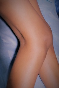
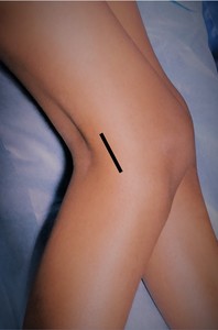
Fig. 4:
LK: Patient position for LK sonography.

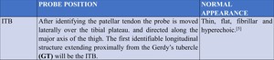
Table 1:
ITB: Probe positioning and normal appearance.

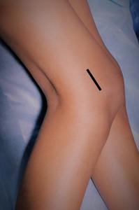
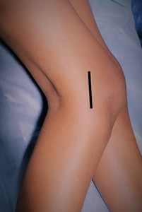
Fig. 5:
ITB - Probe position for evaluation ITB.
 image showing the normal ITB (white arrows). References: Department of Radiology, VMMC and SJH, New Delhi, India")
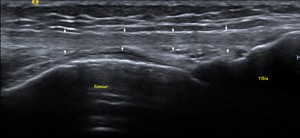
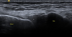
Fig. 6:
ITB – Ultrasound (US) image showing the normal ITB (white arrows).

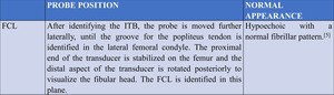
Table 2:
FCL: Probe positioning and normal appearance.

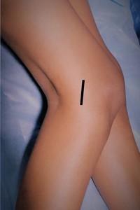
Fig. 8:
FCL: Probe position for evaluation of FCL.
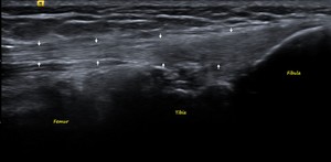
 with its femoral and fibular attachments. References: Department of Radiology, VMMC and SJH, New Delhi, India")
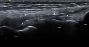
Fig. 9:
FCL: US image showing the normal FCL (white arrows) with its femoral and...

Table 3:
BF: Probe positioning and normal appearance.

Fig. 10:
BF: Probe position for evaluation of BF.
 with its musculotendinous junction and fibular attachment. References: Department of Radiology, VMMC and SJH, New Delhi, India")
Fig. 11:
BF: US image showing the normal BF (white arrows) with its musculotendinous...

Table 4:
POPLITEUS: Probe positioning and normal appearance.
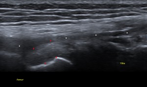
 at its femoral attachment. FCL (white stars) is seen superficial to it. References: Department of Radiology, VMMC and SJH, New Delhi, India")
Fig. 12:
POPLITEUS TENDON - US image showing the normal Popliteus tendon (red arrows) at...

Table 5:
LM: Probe positioning and normal appearance.

Fig. 13:
LM: Probe position for evaluation of LM.
. References: Department of Radiology, VMMC and SJH, New Delhi, India")
Fig. 14:
LM: US image showing the normal homogenous triangular iso-hyperechoic LM (white...

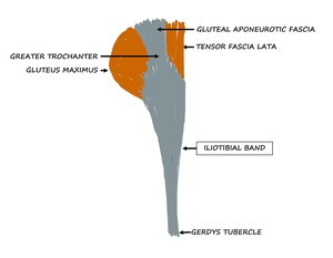
Fig. 15:
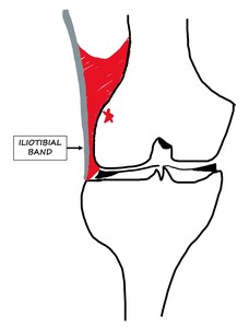
Schematic diagram showing the origin and insertion of the ITB.
, just anterior to the proximal insertion of FCL. PAT TN - Patellar tendon, QT - Quadriceps tendon, PT - Popliteus tendon, BF - Biceps femoris, FCL - Fibular collateral ligament.
References: Department of Radiology, VMMC and SJH, New Delhi, India")
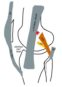
Fig. 16:
ITB - Schematic diagram of LK In Extension - ITB slightly overlies the lateral...
. It also contacts the proximal fibers of the FCL and crosses the popliteus tendon with further flexion. PAT TN - Patellar tendon, QT - Quadriceps tendon, PT - Popliteus tendon, BF - Biceps femoris, FCL - Fibular collateral ligament.
References: Department of Radiology, VMMC and SJH, New Delhi, India")
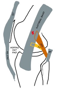
Fig. 17:
ITB: Schematic diagram of LK in Flexion - ITB overlaps the lateral epicondyle...
 that is affected by ITBFS. References: Department of Radiology, VMMC and SJH, New Delhi, India")
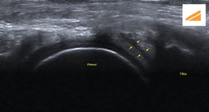
Fig. 18:
ITBFS: The red area is the space between the ITB and lateral epicondyle (red...
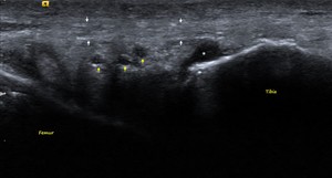
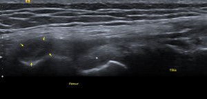
. Few cysts (yellow arrows) and a fluid pocket (white star) are seen within the fat pad posterior to the ITB consistent with formation of adventitious bursae. References: Department of Radiology, VMMC and SJH, New Delhi, India")
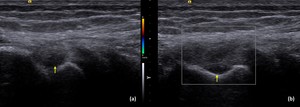
Fig. 19:
ITBFS: US image showing the mildly heterogenous ITB (white arrows). Few cysts...
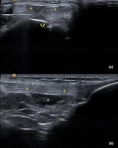
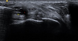
 Pre-injection axial Image of the left anterolateral knee: Shows the ITB (yellow stars) with the needle within the underlying fat (curved yellow arrow).
b) Post-injection longitudinal Image of the left anterolateral knee: Shows the ITB (yellow stars) with the Steroid-LA solution (white star) within the fat.
References: Department of Radiology, VMMC and SJH, New Delhi, India")
Fig. 20:
ITBFS – Intervention: A 28-year-old male runner presented with left lateral...
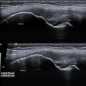
, consistent with mild sprain. Also seen in the image is the normal popliteus tendon (white star) deep and inferior to it. References: Department of Radiology, VMMC and SJH, New Delhi, India")
Fig. 22:
FCL – GRADE 1 INJURY: Longitudinal US image shows hypoechoic thickening of...
 Axial US image shows focal hypoechoic area within the FCL with fiber discontinuity consistent with partial tear (white arrow).
b) Axial US image shows needle tip (curved yellow arrow) within the tear site (white arrow).
References: Department of Radiology, VMMC and SJH, New Delhi, India")
Fig. 23:
FCL – GRADE 2 INJURY:
A 37-year-old male presented with left lateral knee...
, and the attachment of the popliteus tendon at the lateral femoral condyle. References: Department of Radiology, VMMC and SJH, New Delhi, India")
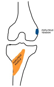
Fig. 25:
POPLITEUS: Schematic diagram of the posterior knee showing the wide attachment...
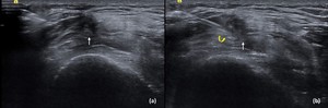
 Longitudinal US image shows a focal hypoechoic area within the popliteus tendon with mild thickening of the tendon at its femoral attachment (yellow arrow). Fiber continuity is maintained.
b) Doppler shows no increased vascularity. Findings are consistent with chronic tendinosis.
References: Department of Radiology, VMMC and SJH, New Delhi, India")
Fig. 26:
POPLITEUS TENDINOSIS:
a) Longitudinal US image shows a focal hypoechoic area...
. References: Department of Radiology, VMMC and SJH, New Delhi, India")
Fig. 27:
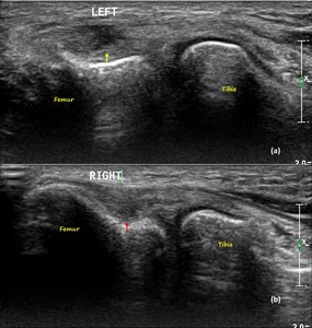
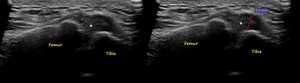
POPLITEUS PARTIAL TEAR: Longitudinal US image showing partial thickness...
 US image of left knee shows high grade partial thickness tear at the non-articular aspect of the popliteus tendon near its femoral attachment (yellow arrow).
b) US image of right knee shows a small focal hypoechoic area within the popliteus tendon at its femoral attachment with maintained fiber continuity (red arrow), consistent with mild tendinosis.
References: Department of Radiology, VMMC and SJH, New Delhi, India")
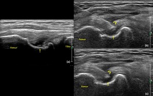
Fig. 28:
POPLITEUS PARTIAL TEAR AND TENDINOSIS:
a) US image of left knee shows high...
 US image of the right knee shows a high grade partial thickness tear of the popliteus tendon at its femoral attachment (yellow arrow).
b and c) US images show needle tip (curved yellow arrow) within the tear site (yellow arrow).
References: Department of Radiology, VMMC and SJH, New Delhi, India")
Fig. 29:
POPLITEUS PARTIAL TEAR WITH INTERVENTION:
A 29-year-old male presented with...

Fig. 30:
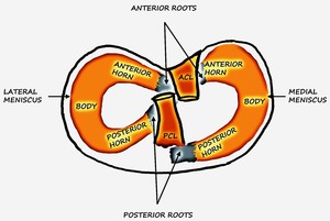
LM: Schematic diagram of the tibial plateau showing the medial and lateral...
,
2 – Black arrows showing the direction of the Horizontal longitudinal tear,
3a – Radial tear,
3b – Parrot beak tear (Displaced radial tear)
References: Department of Radiology, VMMC and SJH, New Delhi, India")
Fig. 31:
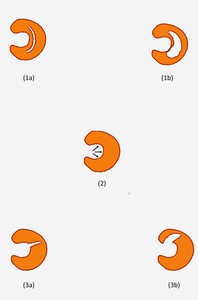
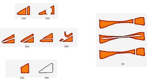
LM TEAR: Schematic diagram showing the three major types of meniscal tears.
1a...

1a – Vertical longitudinal tear; 1b - Bucket handle tear (Displaced vertical longitudinal tear);
2a - Horizontal longitudinal tear; 2b – Flap tear (Displaced Horizontal longitudinal tear);
3a – Radial tear (Truncated meniscus); 3b Radial tear (Ghost meniscus);
4 – From top – bottom –
Vertical longitudinal tear, Horizontal longitudinal tear and Radial tear.
References: Department of Radiology, VMMC and SJH, New Delhi, India")
Fig. 32:
LM TEAR: Schematic diagram showing the three major types of meniscal tears....
 within the lateral meniscus, extending from its periphery up to its inferior articular surface. References: Department of Radiology, VMMC and SJH, New Delhi, India")
Fig. 33:
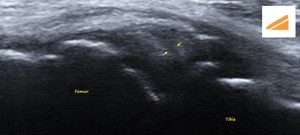
LM - HORIZONTAL LONGITUDINAL TEAR: US image of the lateral knee in the coronal...
 within the lateral meniscus, extending from its periphery up to its inferior articular surface. References: Department of Radiology, VMMC and SJH, New Delhi, India")
Fig. 34:
LM - HORIZONTAL LONGITUDINAL TEAR: US image of the lateral knee of another...
 lateral to the lateral meniscus (white star). References: Department of Radiology, VMMC and SJH, New Delhi, India")
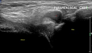
Fig. 35:
PARAMENISCAL CYST: US image of the lateral knee in the coronal plane shows an...
 lateral to the lateral meniscus with needle tip in situ (curved yellow arrow).
References: Department of Radiology, VMMC and SJH, New Delhi, India")
Fig. 36:
PARAMENISCAL CYST - INTERVENTION:
A 42-year-old female patient presented with...
 extending 5mm beyond the tibial plateau margin.
References: Department of Radiology, VMMC and SJH, New Delhi, India")
Fig. 37:
MENISCAL EXTRUSION: US image of the lateral knee in the coronal plane shows...