To simply understanding our dataset will be discussed under four categories.
GROUP I: ERRORS ON CONVENTIONAL SEQUENCES
1.
Pitfalls in acute DVST
In acute DVST (0–5 days),
thrombi generally are isointense on T1W and hypointense T2W images.
This is due to deoxyhemoglobin within the red blood cells trapped in the thrombus meshwork.
As a result,
acute DVST may mimic a normal flow void (1,
2).
CE-MRI or TOF-MRV is essential in diagnosis at this stage (1).
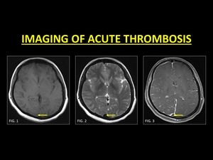
Fig. 1: In the acute stage, a thrombosed vein returns isointense T1W signals (Fig. 1) and hypointense T2W signals (Fig. 2). TOF-MRV or CE-MRI (Fig. 3) is usually required in order the demonstrate the thrombus.
References: Department of Radiology, SevenHills Hospital, India
On unenhanced conventional MR imaging comparison with the signal on the gradient-recalled echo (GRE) sequence is useful.
GRE is sensitive paramagnetic blood breakdown products,
which is appreciated as a hypointense signal (referred to as ‘blooming’).
Blooming within a vein must prompt further imaging (1,3).
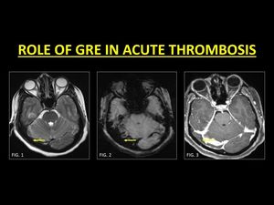
Fig. 2: GRE is a very useful sequence in the identification of an acute thrombus. In the acute stage, thrombi are hypointense on T2W images and therefore may mimic normal flow voids (Fig. 1). The presence of blooming on GRE (Fig. 2) within a vessel represents blood breakdown products and must prompt further imaging in order to confirm thrombosis. CE-MRI (Fig. 3) confirms a filling defect within the right transverse sinus.
References: Department of Radiology, SevenHills Hospital, India
2.
Subacute DVST vs Slow Flow state
Approximately 55 % of patients are imaged in the subacute phase of DVST. In this stage (6 –15 days),
the thrombus is mainly composed of methaemoglobin.
This causes the thrombus to appear hyperintense on both T1W and T2W images (1,
4) which is in sharp contradistinction from in normal flow states (1).
Use of MR Venograms in this phase has its own limitations (discussed subsequently).
Confirmation of a subacute thrombus is best made with the help of contrast administration.
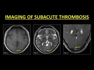
Fig. 3: Most patients are diagnosed in the subacute stage of thrombus evolution. A thrombus in this stage is hyperintense on T1W and T2W images (Fig. 1 and Fig. 2 respectively) and therefore easily identified as a ‘loss of the normal flow void’. CE-MRI is usually performed to support the diagnosis (Fig. 3).
References: Department of Radiology, SevenHills Hospital, India
An important mimic of subacute thrombosis is slow flow states.
Slow flowing blood leads to mobile protons receiving both the 90° and 180° pulses,
thus yielding a signal and mimicking a subacute thrombus (1).
Imaging methods to eliminate this include the use of multiplanar / multisequence imaging,
upstream saturation bands and phase encoding using low velocity-encoding (VENC) gradient.
The easiest and readily available method is the detailed interrogation of GRE images at the same slice.
The absence of 'blooming' indicates the absence of blood breakdown products and confirms patency (5).
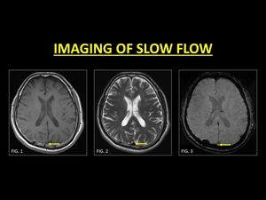
Fig. 4: Generally slow moving blood may demonstrate a bright signal (Fig. 1) on conventional spin echo sequences. A sound knowledge of the appearances of thrombus evolution and confirmation with other sequences (Fig. 2) is essential in aiding a diagnosis. The absence of ‘blooming’ on GRE is an important marker of patency. TOF-MRV or CE-MRI is usually not required in slow flow states.
References: Department of Radiology, SevenHills Hospital, India
3.
Phase Encoding Artifacts (PEA)
PEAs occur due to the motion anatomy following the application of the phase encoding gradient.
This leads to band-like replication of the moving structure across the image occasionally mimicking a thrombus.
On the other hand,
the presence of the artifact can also be used to determine the likelihood of dural sinus patency in equivocal cases,
as only moving structures can generate the artifact (6).
Swapping the direction of the phase and frequency encoding gradients helps in changing the orientation of the artifact,
but doe not eliminate it.
3D Contrast-enhanced Magnetization Prepared Rapid Acquisition Gradient-Echo Imaging Sequence (3D-MPRAGE) are insensitive to these motion-related artifacts the physics of which is beyond the scope of this poster (15)
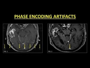
Fig. 5: Phase encoding artifacts can mimic a thrombus. They are identified as a band of replication of moving anatomy along the direction of the phase encoding gradient (Fig. 1). Knowledge of the direction of the gradient used is very useful in identifying the artifacts. MP-RAGE images are known to be devoid of the artifact, which is useful in accurate evaluation of the sinus (Fig. 2).
References: Department of Radiology, SevenHills Hospital, India
GROUP II: ERRORS ON TOF-MR VENOGRAMS
1.
In-plane saturation
TOF imaging relies on the inflow of unsaturated protons in order to produce a bright signal.
The signal intensity is brightest when flow occurs perpendicular to the imaging plane.
When the dural venous sinus is oriented along the imaging plane,
protons are rapidly saturated similar to the rest of the stationary tissues,
causing a loss of signal (7).
Knowing the orientation of acquisition helps radiologists in identifying signal losses due to saturation and avoiding an erroneous diagnosis of thrombosis.
Images from CE-MRI provide a better depiction of all the veins (1).
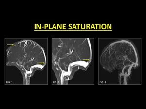
Fig. 6: Unsaturated protons flowing into the imaging plane are required to generate a bright signal. This signal intensity is brightest when the direction of flow is perpendicular to the imaging plane. Portions of the blood vessels which are parallel, are rapidly saturated leading to loss of signal intensity and in the process mimicking a thrombus (Fig. 1, 2). CE-MRI is very useful in order to confirm patency (Fig. 3).
References: Department of Radiology, SevenHills Hospital, India
2. Thrombus 'Shine Through' Effect
Short TR used in TOF images makes it a surrogate for T1W images.
This along with the use of maximum intensity projection (MIP) algorithms to display TOF images cause structures with intrinsic hyperintense T1W signals to ‘shine through’ or appear bright (1,
7,
8).
As discussed,
DVST in the subacute stage is characterized by methaemoglobin which is hyperintense on T1W images.
This causes an artefactual bright signal along the thrombosed vein which may be misinterpreted as a patent lumen.
Close evaluation of GRE images (for the presence of blooming) and inadvertent use of contrast help identify the presence of a thrombus.
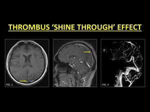
Fig. 7: A sinus thrombus in the subacute stage may have markedly increased signal intensity on T1W images (Fig. 1), which leads to the ‘shine through’ effect on TOF-MRV. This can be misinterpreted as evidence of flow (Fig. 2). Use of CE-MRI techniques in such cases helps to detect filling defects (Fig. 3).
References: Department of Radiology, SevenHills Hospital, India
3.
Sinus Hypoplasia and Flow Gaps
Hypoplasia of sinuses is common,
especially of the transverse sinus (TS).
Often the right TS is larger than the left (1).
The medial part of the TS is more commonly atretic or hypoplastic (1).
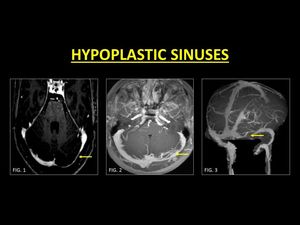
Fig. 8: Hypoplasia of the transverse sinus is very common. Usually the left transverse sinus is hypoplastic (Fig. 1, 2, 3).
References: Department of Radiology, SevenHills Hospital, India
Flow gaps are common phenomena on TOF-MRV.
They occur within non-dominant transverse sinuses and are characterized by an abrupt loss of flow signal in an otherwise patent sinus (1).
The genesis of this artifact is complex and is thought to occur due to a combination of a small sinus size,
slow flow,
and an acquisition plane that is not perpendicular to the sinus (1,
9).
Careful assessment of the source images and the lack of expected thrombus signal on conventional sequences are helpful clues to avoid this pitfall.
Flow gaps are almost unknown in contrast-enhanced images (1).
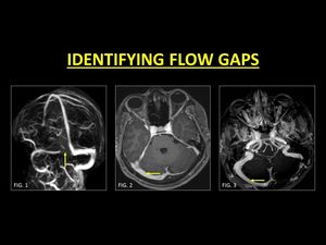
Fig. 9: Flow gaps are seen in the non-dominant sinus (Fig. 1) on TOF-MRV images. As these can mimic a focal thrombus, confirmation with CE-MRI is generally indicated. Reconstructions following contrast administration helps in delineating the entire length of the sinus, therefore confirming normalcy (Fig. 3, 4).
References: Department of Radiology, SevenHills Hospital, India
4.
Partial recanalization
Following medical management of DVST,
partial recanalization of the sinus is common.
Complete recanalization is not necessary for clinical recovery,
and the extent of recanalization may not correlate closely with the clinical outcome (10).
TOF-MRV poses a challenge to the radiologist as areas of a signal void can be thought to be due to in-plane saturation. CE-MRI is excellent in confirming the presence of residual thrombosis / partial recanalization as it is devoid of saturation effects.
However,
if image acquisition is delayed at CE-MRI,
the residual thrombus may also enhance and simulate patency (11).
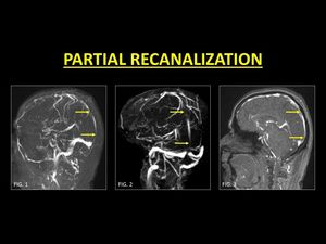
Fig. 10: Following medical management, thrombosed veins may not recanalize completely. On Phase contrast (Fig. 1) and TOF-MRV (Fig. 2) of the sinus areas of signal drop may be seen, representing residual thrombus. This is especially important on TOF-MRV as it may be interpreted as in-plane saturation. CE-MRI is always necessary to demonstrate partial recanalization (Fig. 3).
References: Department of Radiology, SevenHills Hospital, India
GROUP III: ERRORS ON CONTRAST ENHANCED SCANS:
1.
Chronic Thrombosis
As thrombi enter the chronic phase of evolution (15 days and beyond) their signal intensity is highly variable (1,
12).
As a general rule in this stage,
the thrombus appears hypo-isointense on T1W and T2W images.
However,
the signal intensity may occasionally mimic slow flowing blood.
Following contrast administration,
a chronic thrombus may enhance (11).
Such enhancement is thought to be due to intrinsic vascularization in the process of clot organization as well as the development of intra-thrombus collateral channels (13). TOF-MRV is helpful in identifying true occlusions.
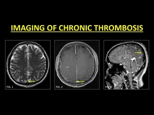
Fig. 11: Chronic DVST may occasionally mimic slow flowing blood (Fig. 1). Post contrast images may demonstrate enhancement within the sinus, even in the presence of a chronic thrombus due to intrinsic vascularization occurring during clot organization (Fig. 2). As this may be erroneously interpreted as a patent sinus, TOF-MRV must be used to identify true occlusions.
References: Department of Radiology, SevenHills Hospital, India
2.
Arachnoid Granulations (AGs)
AGs are normal structures that project into the lumen of dural sinuses and are responsible for the resorption of CSF.
They occur throughout the dural sinuses but are commonly noted along the transverse sinuses (14).
When prominent,
they tend to appear as filling defects on post-contrast images but follow CSF intensity on pulse sequences and appear as focal rounded filling defects along typical anatomic distribution,
which are features that help in differentiating them from a thrombus (14,
15).
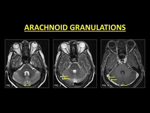
Fig. 12: Arachnoid granulations are normal structures that project within the lumen of dural sinuses. They follow CSF signal intensity (Fig. 1, 2) and when prominent, appear as filling defects on post contrast. Signal characteristics and focal rounded filling defects along typical anatomic distribution guide in diagnosing arachnoid granulations.
References: Department of Radiology, SevenHills Hospital, India
3.
Intrasinus septations:
Intrasinus fibrotic bands or septations are normal structures within the dural sinuses and are best seen on contrast-enhanced 3D-MPRAGE images (15).
They are frequently seen in the straight and the transverse sinuses oriented along their long axis and conforming to the shape of the sinus (15).
These structures appear as filling defects on contrast-enhanced images.
In comparison with partially recanalized DVST,
these septations produce thin defects with sharp margins.
Occasionally,
an arachnoid granulation may be seen on end of the septation (15).
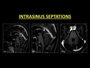
Fig. 13: Intrasinus fibrotic bands or septations are best seen on MP-RAGE images. These are usually seen in the straight (Fig. 1, 2) and the transverse sinus (Fig. 3), oriented along the long axis of the sinus. Septations produce thin defects with sharp margins as opposed to thrombi.
References: Department of Radiology, SevenHills Hospital, India
4.
Idiopathic Intracranial Hypertension (IIH) and Intrasinus stents
IIH is a syndrome of increased intracranial pressure without an obvious etiology.
Sinus thrombosis is known to occur as part of the intracranial hypertension syndrome,
therefore,
must be ruled out in all patients with IIH.
Bilateral transverse sinuses stenosis without antecedent or current thrombosis has been described as an imaging feature of IIH (16).
These stenotic segments are often seen in the lateral segments of the transverse sinus and may mimic chronically thrombosed veins (1,16).
CE-MRI may be more useful than TOF-MRV to demonstrate patency.
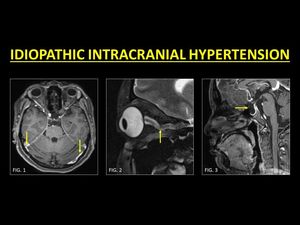
Fig. 14: Idiopathic intracranial hypertension (IIH) is a condition known to be associated with stenosis of both the transverse sinuses as well as DVST. In patients with IIH, a thorough examination of the venous sinuses is warranted and CE-MRI is usually used to ensure patency of stenosed sinuses (Fig. 1). Other imaging features include prominence of peri-optic sheath and tortuosity of the optic nerves (Fig. 2) and an empty sella (Fig. 3).
References: Department of Radiology, SevenHills Hospital, India
Whether sinus stenosis is a cause or result of IIH is a topic of ongoing study.
An improvement of symptoms has been noticed in patients with IIH and sinus stenosis following the placement of stents in the transverse sinus (17).
The dural venous sinus stents on post-contrast scans appear as filling defects,
therefore,
obtaining relevant clinical details before labeling it as a thrombus is a must.
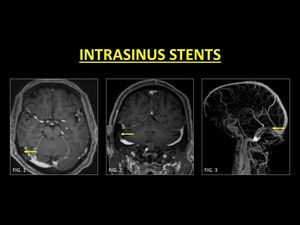
Fig. 15: Placement of stents in the transverse sinus have been associated with reduction in symptoms of IIH. Following contrast administration, stents appear as filling defects. Obtaining history of previous intervention is critical in avoiding a misdiagnosis as thrombus (Fig. 1, 2, 3).
References: Department of Radiology, SevenHills Hospital, India
GROUP IV: IDENTIFYING SECONDARY CAUSES OF DVST
Identifying the etiology of a DVST is critical in management and the outcome.
Thrombus within a sinus is generally bland and is due to intrinsic alterations of the clotting system,
dehydration or hormonal changes (eg.
pregnancy,
puerperium,
and drug-induced).
DVST in these cases can be treated using standard anticoagulation therapy.
However,
in some cases,
mere anticoagulation therapy may not suffice.
One such important example is sino-venous thrombosis in patients with mastoiditis.
Thrombosed sinuses in these cases require aggressive treatment including a combination of anticoagulation and antibiotics (18).
Similarly,
intracranial masses,
especially those along the course of the sinuses tend to invade sinuses.
Identification of tumor invasion and is key in ensuring accurate presurgical planning and optimal debulking (19).
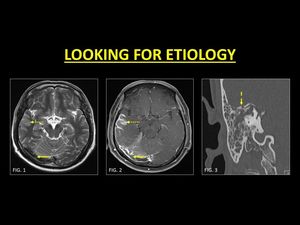
Fig. 16: A complication of mastoiditis is sinovenous thrombosis. A careful evaluation of the brain and adjacent structures must be performed in all cases of DVST. Note the thrombosed right transverse sinus (Fig. 1, 2) with cerebritis along the right temporal lobe (dotted arrows in Fig. 1, 2). HRCT of the temporal bone revealed fluid opacification in the mastoid sinus with destruction of the tegmen tympani (dash arrow in Fig. 3). Aggressive antibiotics in conjunction with anticoagulation was provided to the patient.
References: Department of Radiology, SevenHills Hospital, India
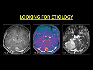
Fig. 17: In patients with intracranial masses, especially those along the dural sinuses, examination for intrasinus invasion is a must. This helps in in adequate pre-operative planning and ensures optimal debulking. Note the invasion of the torcular herophili and the left transverse sinus in a patient with a medulloblastoma (Fig. 1, 2). Posterior fossa meningiomas along the cerebellar hemispheres also invade the dural sinuses (Fig. 3).
References: Department of Radiology, SevenHills Hospital, India

 and hypointense T2W signals (Fig. 2). TOF-MRV or CE-MRI (Fig. 3) is usually required in order the demonstrate the thrombus. References: Department of Radiology, SevenHills Hospital, India")
. The presence of blooming on GRE (Fig. 2) within a vessel represents blood breakdown products and must prompt further imaging in order to confirm thrombosis. CE-MRI (Fig. 3) confirms a filling defect within the right transverse sinus. References: Department of Radiology, SevenHills Hospital, India")
 and therefore easily identified as a ‘loss of the normal flow void’. CE-MRI is usually performed to support the diagnosis (Fig. 3).
References: Department of Radiology, SevenHills Hospital, India")
 on conventional spin echo sequences. A sound knowledge of the appearances of thrombus evolution and confirmation with other sequences (Fig. 2) is essential in aiding a diagnosis. The absence of ‘blooming’ on GRE is an important marker of patency. TOF-MRV or CE-MRI is usually not required in slow flow states. References: Department of Radiology, SevenHills Hospital, India")
. Knowledge of the direction of the gradient used is very useful in identifying the artifacts. MP-RAGE images are known to be devoid of the artifact, which is useful in accurate evaluation of the sinus (Fig. 2). References: Department of Radiology, SevenHills Hospital, India")
. CE-MRI is very useful in order to confirm patency (Fig. 3). References: Department of Radiology, SevenHills Hospital, India")
, which leads to the ‘shine through’ effect on TOF-MRV. This can be misinterpreted as evidence of flow (Fig. 2). Use of CE-MRI techniques in such cases helps to detect filling defects (Fig. 3). References: Department of Radiology, SevenHills Hospital, India")
.
References: Department of Radiology, SevenHills Hospital, India")
 on TOF-MRV images. As these can mimic a focal thrombus, confirmation with CE-MRI is generally indicated. Reconstructions following contrast administration helps in delineating the entire length of the sinus, therefore confirming normalcy (Fig. 3, 4).
References: Department of Radiology, SevenHills Hospital, India")
 and TOF-MRV (Fig. 2) of the sinus areas of signal drop may be seen, representing residual thrombus. This is especially important on TOF-MRV as it may be interpreted as in-plane saturation. CE-MRI is always necessary to demonstrate partial recanalization (Fig. 3). References: Department of Radiology, SevenHills Hospital, India")
. Post contrast images may demonstrate enhancement within the sinus, even in the presence of a chronic thrombus due to intrinsic vascularization occurring during clot organization (Fig. 2). As this may be erroneously interpreted as a patent sinus, TOF-MRV must be used to identify true occlusions.
References: Department of Radiology, SevenHills Hospital, India")
 and when prominent, appear as filling defects on post contrast. Signal characteristics and focal rounded filling defects along typical anatomic distribution guide in diagnosing arachnoid granulations. References: Department of Radiology, SevenHills Hospital, India")
 and the transverse sinus (Fig. 3), oriented along the long axis of the sinus. Septations produce thin defects with sharp margins as opposed to thrombi. References: Department of Radiology, SevenHills Hospital, India")
 is a condition known to be associated with stenosis of both the transverse sinuses as well as DVST. In patients with IIH, a thorough examination of the venous sinuses is warranted and CE-MRI is usually used to ensure patency of stenosed sinuses (Fig. 1). Other imaging features include prominence of peri-optic sheath and tortuosity of the optic nerves (Fig. 2) and an empty sella (Fig. 3). References: Department of Radiology, SevenHills Hospital, India")
. References: Department of Radiology, SevenHills Hospital, India")
 with cerebritis along the right temporal lobe (dotted arrows in Fig. 1, 2). HRCT of the temporal bone revealed fluid opacification in the mastoid sinus with destruction of the tegmen tympani (dash arrow in Fig. 3). Aggressive antibiotics in conjunction with anticoagulation was provided to the patient. References: Department of Radiology, SevenHills Hospital, India")
. Posterior fossa meningiomas along the cerebellar hemispheres also invade the dural sinuses (Fig. 3). References: Department of Radiology, SevenHills Hospital, India")