Study Design
A retrospective study using data obtained from computed tomography (CT) of adult patients will be used. 3D volume reconstructions of the pelvis were used to take the various measurements of the anterior and posterior acetabular column in 281 patients (156 male and 125 female) with exclusion criteria being previous trauma and fractures of the pelvis,
congenital abnormalities and tumours involving the bony pelvis.
Setting
Steve Biko Academic Hospital,
University of Pretoria,
Pretoria,
Gauteng,
South Africa.
Patient Selection
Selection of patients was sequential and included adult patients undergoing computed tomography (CT) of the pelvis (for other indications) at Steve Biko Academic Hospital on a Siemens Sensation Somatom 64 slice CT scanner (Serial number 3519,
Germany).
Patients selected were adults 20 years of age or older who had undergone CT of the abdomen and pelvis for other indications e.g.
renal stones,
gastrointestinal malignancy etc.
Exclusion criteria – Any patients with previous fractures of the lumbar spine,
pelvis,
hips or femurs as recorded in the referral card,
in the notes or noted on CT were excluded.
Any patients with congenital abnormalities; tumours of the bony pelvis or other lesions involving the bony pelvis were also excluded.
Interpretation of Imaging
3D volume reconstruction of the surface anatomy of the bony pelvis was then performed using the available CT data and utilizing the proprietary Siemens software.
These 3D volume reconstructions of the surface anatomy of the pelvis were thereafter used to produce sagittal and antero-posterior views of the posterior columns by cutting through the volume re-constructions in the trajectory of the screw placements in various planes.
Further reconstructions were made of the anterior column by rotating the image to obtain a profile view of the anterior column and again cutting through in the plane of the screw placements.
Cutting through in the screw placement trajectory on an inlet view was performed to obtain the second view of the anterior column.
The rationale of cutting through the columns in the plane of the screw trajectory was to avoid any mis-representation of measurements by only using the surface anatomy of the 3D volume rendered images.
The correct measurements of length,
width and height were therefore made in the correct plane and at the correct depth relative to screw placement.
Once the reconstructions had been made with the above manipulations a reference grid was palced onto the final image in order to assist with correct calibration of measurements and for accuracy in measurements.
The above reconstructions were then used to take predetermined measurements of the anterior and posterior columns of the acetabulum as depicted in Figures 1 – 4 below.
A single senior radiographer was utilised to obtained the reconstructions,
and the same radiographer was utilized throughout the study to minimize training times as well as inter-radiographer variability in reconstruction planes and views.
A single radiologist for the same reasons made measurements.
There was however validation of measurements by a second reader (a qualified consultant radiologist) in order to ensure accuracy and reproducibility of the measurements taken.
Anterior Column Measurements
1.
Length: From 3mm superior to the inferior tubercle of the pubic symphysis (parallel to a line drawn in the plane of the anterior aspect of the symphysis pubis on the obturator oblique view) through the superior pubic ramus to the posterior acetabular margin,
on the obturator oblique views.
(Fig. 4).
2.
Width: Measurement at the narrowest point on the pelvic inlet view reconstruction.
(Fig. 5).
3.
Height: Measurement of the narrowest point at the mid-acetabular roof on the obturator oblique view.
Using the line drawn for the length as a reference point for the mid-point of a screw placed through to the anterior column.
(Fig. 4).
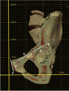
Fig. 4: Obturator oblique reconstruction view of the left hemi-pelvis with the anterior column seen in profile. Note the reference grid super-imposed onto the image for accurate calibration.
Lines as labeled in image depict:
1. Reference line drawn in the cranio-caudal plane of the symphysis pubis.
2. Line parallel to 1 from the inferior pubic tubercle 3mm superiorly to reach the entry point of a percutaneous fixation screw placed through the anterior column.
3. Line from the point 3mm superior to the inferior pubic tubercle to the acetabular rim in the trajectory of the percutaneous fixation screw to give the length of the anterior column. Placement of this line will have to ensure that there is no cortical breach at any point in the line.
4. Narrowest point from line 3 to the cortex of the superior aspect of the superior pubic ramus.
5. Narrowest point from line 3 to the cortex of the acetabular roof.
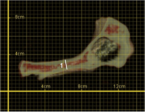
Fig. 5: Inlet reconstruction view of the left hemi-pelvis cutting through the anterior column in the axial plane to give the narrowest width (1).
Posterior Column Measurements
1.
Length: Measurement from the most inferior aspect of the ischial tuberosity to the sciatic notch on the posterior-anterior reconstruction view.
(Fig. 6).
2.
Transverse Width: Measurement of the narrowest point to the line drawn for the length from the medial cortex of the ischium using the most medial aspect of the acetabular wall as a reference point.
( Fig. 6 ).
3.
Antero-posterior Width: Measurement of the narrowest points to the cortex at the mid-acetabular posterior wall on the sagittal view with the mid-point being a line similar to the line used above for the length in Fig. 6 .
(Fig. 7).
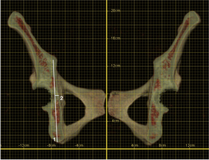
Fig. 6: Postero-anterior reconstruction view of the pelvis to view the posterior column in profile.
Lines as labeled in image above depict:
1. Length of the posterior column from the most inferior point of the ischial tuberosity to the level of the sciatic notch in the trajectory of the percutaneous fixation screw.
2. Transverse Width – measurement of the narrowest point to the line drawn for the length from the medial cortex of the ischium using the most medial aspect of the acetabular wall as a reference point.

Fig. 7: Sagittal reconstruction view depicting the posterior column in profile.
Lines as labeled in image above depict:
1. Trajectory of the percutaneous fixation screw from the most inferior point of the ischial tuberosity to the level of the sciatic notch.
2. Narrowest point from the reference line (1) to the anterior cortex of the ischium.
3. Narrowest point from the reference line (1) to the posterior cortex using the most posterior aspect of the acetabular wall as a reference point.
4. Narrowest point from the reference line (1) to the posterior cortex of the iliac wing at the sciatic notch.
The heights and widths obtained were correlated to the radii of screws placed in the trajectory,
therefore measurements were of a functional diameter of the various columns.
Further measurements were made of the maximal diameter of the head of the femur (Fig. 8) as well as the maximal width of the neck of the femur (Fig. 9) of each patient on the axial and coronal views respectively of the CT multiplanar reformats.
These measurements were used to compare with the measurements obtained in the above reconstructions and to ascertain if there is any statistical correlation or reliable ratio that can be gleaned in order to further facilitate screw selection in settings where 3D reconstruction capabilities are lacking.
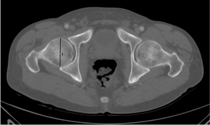
Fig. 8: Axial CT image of a patient with bone windowing. Maximal diameter of the femoral head (1) measured in the axial plane.
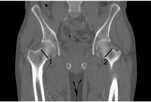
Fig. 9: Coronal CT image of a patient with bone windowing. Maximal widths of the femoral necks (1 & 2) measured in the coronal plane.
Statistical Analysis
Of primary interest is the potential relationship between the easily obtained femoral head and neck measurements with the measurements of the column widths on the 3D reconstructions. However actual measurements of the column heights and widths and correlation with safe sizes of percutaneous screws that can be utilized are also useful and relevant to clinical practice of this novel surgical approach.
Sample Size
A sample size of approximately 281 patients was obtained with a 156:125 split between males and females.
This yielded a power of greater than 95% for the primary objective i.e.
the relationship between individual column size and diameters of the femoral head and neck.
Data Analysis
Collected data was collated in a spreadsheet,
with each patient assigned a study number for anonymity.
Means,
standard deviations at 95% confidence intervals were determined for the column measurements as well as femoral head and neck measurements.
To assess the relationship between the minimum column widths/ percutaneous screw widths in the two respective planes and the femur head and neck diameters multiple linear regression was employed.
Testing of regression coefficients will be at the 0.05 level of significance.
If necessary non-linear terms may be included for the femoral head and neck measurements and relationship to the column measurements.


.")

 to the anterior cortex of the ischium.
3. Narrowest point from the reference line (1) to the posterior cortex using the most posterior aspect of the acetabular wall as a reference point.
4. Narrowest point from the reference line (1) to the posterior cortex of the iliac wing at the sciatic notch.")
 measured in the axial plane.")
 measured in the coronal plane.")