ARTIFACTS DUE TO ACQUISITION
These artifacts are primarily truncation artifacts due to the limited size of the detector and of the x-ray beam.
a) Bright area artifact- where the detector cant see [6]

Fig. 4: Bright area (arrow) at extreme ends of image
References: Department of Radiology, All India Institute of Medical Sciences, New Delhi
WHY DOES IT HAPPEN ?
The area marked (a) attenuates the beam when the tube is in position (A) and is projected to area (a') on the detector.
The detector however is unaware of the presence of breast tissue in the marked area.
The attenuation caused by this area is added to the most peripheral part of the breast tissue included by the detector.
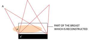
Fig. 5: Genesis of bright area artifact- due to limited detector size
b) Staircase artifact- where the beam cant see [6]
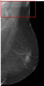
Fig. 6: Presence of multiple lines at the ends of the image giving a 'staircase-like' appearance
References: Department of Radiology, All India Institute of Medical Sciences, New Delhi
WHY DOES IT HAPPEN
At each tube position there is a corresponding part of the breast tissue that would not be projected back by the detector.
The breast seemingly ends at different places for different tube positions leading to the production of lines at the edges of the image.

Fig. 7: Genesis of staircase artifact- due to limited beam size
ARTIFACTS DUE TO RECONSTRUCTION
a) Blurr and ripple-
A high density structure though blurred,
remains visible in sections apart from the one in which it is actually located [7].
This phenomenon is particularly marked with high intensity structures like calcifications (fig 8)

Fig. 8: Calcification in slice 1 ( where it is actually located) is progressively blurred as we scroll laterally. It remains visible in slice 2,3 and 4, although blurred, though it is not actually located at these locations in the breast.
Note the staircase artifact in the lateral most section (4)
References: Department of Radiology, All India Institute of Medical Sciences, New Delhi
WHY DOES IT HAPPEN
These artifacts occur due to incomplete cancellation of objects outside the plane of interest.

Fig. 9: The genesis of Blurr and ripple artifact.The mid-plane represents the actual location of the structure. This structure however continues to be seen in adjacent planes as well.
This phenomenon is more marked when the high intensity structure is oriented perpendicular to the sweep direction[7] ( fig 10)

Fig. 10: Image 1- Digital mammography MLO view. Image 2-5 tomosynthesis images. Clip a shows more blur than clip b due to its perpendicular orientation to sweep direction.
Note that blur becomes a ripple as we scroll away from the actual plane of the object of interest
References: Department of Radiology, All India Institute of Medical Sciences, New Delhi
As the distance of the plane of interest increases from the high density object the blur gets transformed into a ripple[7].
(fig 10)
Though clearly recognizable in case of calcifications and surgical clips,
structures of intermediate density like prominent trabeculae are more difficult to recognize.
Tomosynthesis has shown to be more accurate than digital mammography in measuring size of masses [8].
In our experience,
masses may appear falsely larger due to incomplete blurring of prominent trabecula adjacent to it if the mass if measured in the wrong section (where the margins are not seen the best).
( Fig 11)
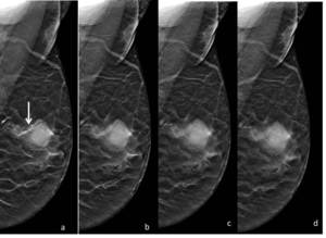
Fig. 11: Tomosynthesis images of the breast MLO view.
In a)the margins of the mass are best seen. A prominent trabecula is also seen adjacent to the mass (arrow)
The mass and trabecula are subsequently blurred as we scroll laterally and in d appear to make a single larger mass
References: Department of Radiology, All India Institute of Medical Sciences, New Delhi
Similarly in (fig 12) skin appears thicker than it actually is due to incomplete blurring of the skin of a more medial section.

Fig. 12: Skin of the breast (inferior to the nipple)in section (a) has not been adequately blurred as we scroll to adjacent sections. In section (c)the skin appears thicker that it actually is.
References: Department of Radiology, All India Institute of Medical Sciences, New Delhi
LEARNING POINT : Always scroll to define margins only in the plane in which it is the clearest.
Beware : a distorted,
incompletely cancelled trabecula may falsely appear as a suspicious mass on a different section.
b) Halo artifact-
Reconstruction of very low signal around a high density object such as calcifications leads to the production of a halo.
The halos particularly pronounced along the sweep direction[7].
(fig 13)

Fig. 13: Halo artifact : reconstruction of very low density around a high density structure
References: Department of Radiology, All India Institute of Medical Sciences, New Delhi
ALTERING IMAGING PARAMETERS- CAN WE AVOID ARTIFACTS?
It is known a priori that the artifacts depend on 2 important factors-
1) Number of projections- can they be increased ?
Increasing the number of projections at the same total exposure level,
means a decreased dose per exposure --> increased noise in the image [5]
2) Angular range of projections- can we get closer to 180 ?
Increased angle means increased obliquity --> lower spatial resolution[5]
In short,
there is no free meal in tomosynthesis – imaging parameters are a trade-off between z-axis accuracy,
spatial resolution and importantly,
radiation exposure to the breast.
