In order to determine the exact location and intensity of each echo and to produce an ultrasound image,
the equipment - despite its continuous development - still relies on the following basic physical assumptions:
1.
The pulse of ultrasound and its echo travel in a straight line.
2.
The resulted echo returns to the transducer after a single reflection.
3.
The time taken for an ultrasound to return to the transducer as an echo,
time of flight,
is directly related to the depth of an object.
4.
The speed of sound in human tissue is constant and set at 1540 m/sec.
5.
The returning echoes are presumed to originate from the center of the ultrasound beam and are thus displayed within the central vector,
representing the original beam.
6.
The acoustic energy is uniformly attenuated and the intensity of the resulted echo depends only on the acoustic properties and the interface size.
Often,
the basic assumptions cannot be maintained and the machine is not able to differentiate deviations from these principles.
Therefore,
echoes that do not correspond to the position or intensity of the original interface may be erroneously displayed and perceived as artifacts.
In grey-scale imaging,
artifacts may arise due to unavoidable errors related to the ultrasound beam characteristics,
the presence of multiple echo paths,
velocity errors and attenuation errors.
The color Doppler technique is also prone to artifacts,
which can be even more troublesome than those on grey-scale imaging.
Beam-width artifact
This artifact is identifiable after the complete understanding of the shape of the ultrasound beam.
At the exit from the transducer,
the main ultrasound beam is approximately as wide as the transducer,
then it narrows at the approach of the focal zone and widens again after it has passed the focal zone.
The distal widening may exceed the actual width of the transducer and a highly reflective object located within this widened beam may produce echoes.
The machine assumes that these echoes arise from within the narrowed,
focal zone and displays them as such.
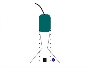
Fig. 12: Beam-width artifact - The ultrasound machine assumes that echoes return only from the plane indicated by the dotted lines. In reality, the ultrasound beam narrows towards and widens distal to the focal zone. If an object lies within the widened beam, in the peripheral area (purple circle), the echoes generated by it are falsely displayed as overlapping the object of interest (green square).
References: Adriana Calin, Cluj-Napoca
Recognition: Clinically,
this artifact should be taken into consideration when a structure that should have an anechoic appearance contains peripheral echoes.
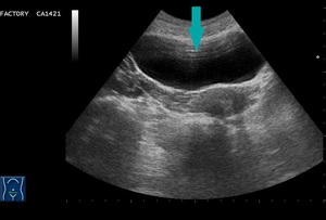
Fig. 1: Transverse view of the urinary bladder - multiple echoes inside the expected anechoic structure (blue arrow).
Significance: These low-level echoes within anechoic or cystic structures can cause the wall to appear thickened and indistinct.
They can be mistaken for debris,
sludge,
gravel or clotted blood.
Improvement: By repositioning the patient,
adjusting the focus to the level of interest and placing the transducer at the center of the examined object,
the generated echoes will diminish.
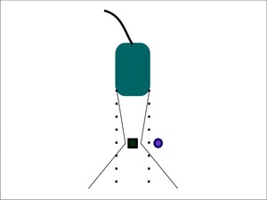
Fig. 13: Correction of the beam-width artifact - By placing the object of interest (green square) within the center of the focal zone, the falsely displayed echoes generated by the peripheral object (purple circle) will disappear.
References: Adriana Calin, Cluj-Napoca
Side-lobe artifact
Side-lobes represent multiple beams of low amplitude that arise radially from the main ultrasound beam axis.
They are generated by the radial expansion of the piezoelectric crystals and are mainly produced by linear-array transducers.
If a strong reflector is located in the path of these low-energy,
off-axis pulses,
echoes may result,
but they will be interpreted as having originated from within the main beam and displayed as such.
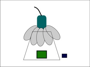
Fig. 14: Side-lobe artifact - When the multiple off-axis beams of ultrasound, also known as side-lobes (grey ellipses), encounter and object (purple square), the machine assumes that the corresponding returning echoes come from the main beam. Therefore, on the display, the object appears misplaced and duplicated.
References: Adriana Calin, Cluj-Napoca
Recognition: Curved,
superfluous echoes within anechoic structures.
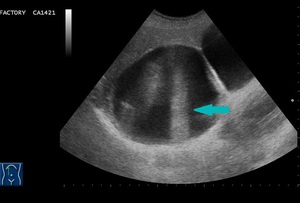
Fig. 2: Longitudinal view - multiple falsely displayed echoes within a cystic lesion (blue arrow).
Significance: Additional,
unnecessary echoes may be mistaken for septa or sediment
Improvement: By angling the transducer or changing the scan plane,
the false echoes will disappear.
Reverberation artifact
This artifact derives from the erroneous assumption that the echo returns to the transducer after a single reflection and that the depth of an interface is related to the time necessary for this round trip.
When the ultrasound beam encounters two highly reflective surfaces,
the echoes may be relentlessly reflected back and forth before returning to the transducer for detection and display.
This will result in multiple echoes,
which will be recorded and displayed.
The only echo that will be displayed in the proper location is the echo that returns after a single reflection.
The ensuing echoes will take longer to return to the transducer and the processor will incorrectly assume that the delay is the result of an increased distance from the transducer.
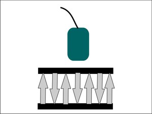
Fig. 15: Reverberation artifact - Between two highly reflective interfaces, ultrasound echoes (grey arrows) will be repeatedly reflected.
References: Adriana Calin, Cluj-Napoca
Recognition: On the image,
multiple equidistantly spaced linear reflections will appear,
known as the reverberation artifact.
It is generated when the ultrasound beam is perpendicular to a strong reflector,
to a soft tissue-air interface or to the abdominal wall with a considerable depth of subcutaneous tissue.
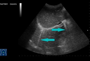
Fig. 3: Transverse abdominal scan - reverberations (blue arrow).
Significance: This troublesome artifact is consistently present in anechoic organs,
but can also appear in solid organs,
can mimic highly echoic structures and also obscure superficial metastases or cysts.
Improvement:
Besides changing the direction of the beam,
tissue harmonic imaging (THI) can be very useful in the presence of reverberations.
Tissue harmonic imaging consists in sound waves formed within the body by the interaction of the fundamental pulse and the tissue.
Low amplitude,
high frequency waves will be generated,
while the fundamental wave will be suppressed by various means.
It helps in clearing the image,
especially that of anechoic structures or cystic lesions.
Comet tail artifact
The comet tail artifact represents a special form of reverberation.
It occurs when the two highly reflective interfaces are closely spaced.
In this case,
the resulting sequential echoes are so close together,
that an individual signal is not detectable.
Additionally,
the later echoes may have decreased amplitude due to attenuation and consequently,
a decreased width.
The result will be an artifact caused by the principle of reverberation but with a triangular,
tapered shape.
Recognition: The comet tail artifact appears as a dense tapering trail of echoes just distal to a strongly reflecting structure.
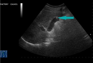
Fig. 4: Longitudinal abdominal scan - comet-tail artifact produced by a cholesterol polyp (blue arrow).
Significance: This finding is visible in the presence of small renal or ureteric calculi,
small common bile duct stones,
adenomyomatosis of the gallbladder,
pancreatic calcifications,
testicular microlithiasis or foreign bodies,
such as surgical clips,
glass,
metal and can be helpful in establishing a diagnosis.
Ring-down artifact
The ring-down artifact,
another special form of reverberation,
is generated by the resonant vibrations caused by the transmitted US energy within the fluid trapped between four bubbles of air (tetrahedron of bubbles).
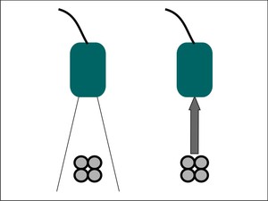
Fig. 16: Ring-down artifact - When the main ultrasound beam encounters a tetrahedron of bubbles with fluid trapped between them, the vibrations from the collection cause an energy that returns to the transducer and is displayed by the machine.
References: Adriana Calin, Cluj-Napoca
Recognition: This phenomenon will be displayed as a streak or series of parallel bands radiating posteriorly to a gas collection.
Significance: Useful in detection of gas collection and in prediction of pulmonary abnormalities.
Mirror image artifact
This artifact is the result of the false assumption that an echo returns to the transducer after a single reflection.
In this case,
the primary ultrasound beam encounters a highly reflective interface.
Before returning to the transducer,
the echoes encounter the ”back side” of another structure and are reflected back to the highly reflective interface.
This will lead to the image of a duplicated structure,
located equidistantly,
but deep from the strong reflective interface.
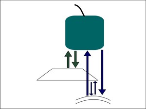
Fig. 17: Mirror image artifact - Besides the expected reflected echoes, which are displayed properly (green arrows), an alternative path (purple arrows) encounters a deeper reflective interface first. The resulting echoes from the alternative path take longer to return to the transducer and are erroneously placed on the display.
References: Adriana Calin, Cluj-Napoca
Recognition: A duplicated image,
commonly identified at the level of the diaphragm,
where the highly reflector is represented by the pleural-air interface.
Hepatic parenchyma is falsely seen in the location of the lung parenchyma.
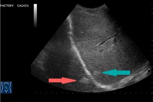
Fig. 5: Oblique abdominal view - mirror image artifact in a patient with hepatic metastases. The original echogenic lesion is located in the right lobe of the liver (blue arrow), while the duplicated echogenic one is projected in the expected lung area, equidistant from the diaphragm (pink arrow).
Attenuation artifacts
When the ultrasound beam travels through the body,
its energy becomes attenuated.
The longer the path an echo has to travel,
the more it will be attenuated.
The processer is able to compensate amplification of the echoes that take longer to return to the transducer,
making the image uniform.
The best tool for compensation is the time gain compensation (TGC),
which helps the user in making the image uniform.
When the ultrasound beam encounters a focal material that attenuates the sound to a greater or lesser extent than in the surrounding tissue,
the strength of the beam distal to this structure will be either weaker or stronger than in the surrounding field.
Acoustic shadowing
When the ultrasound beam encounters a strongly attenuating or highly reflective interface,
the amplitude of the beam distal to this structure and the echoes returning from structures beyond the highly attenuating structure will be diminished.
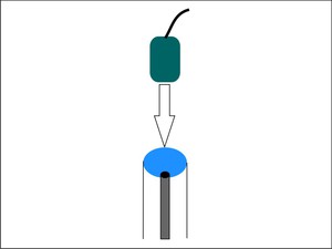
Fig. 18: Acoustic shadowing - The echoes received distally to a strong attenuating tissue (black point) are lower in intensity in comparison to other echoes received from similar depth.
References: Adriana Calin, Cluj-Napoca
Recognition: In clinical imaging,
this phenomenon is recognized as a dark or hypoechoic band known as a “shadow” deep to a highly attenuating structure.
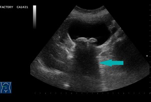
Fig. 6: Transverse abdominal scan - acoustic shadowing (blue arrow) in a case of gallstones.
Significance: Complete shadowing does not induce confusion to the physician and is extremely helpful in confirming a gallstone or a renal stone.
If the shadowing is incomplete due to a difference between the width of the beam and the diameter of the calculus,
it can be troublesome.
If the stone is smaller than the beam,
some of the sound will go around the stone and echoes will return from the deeper structures or there may be no shadow at all.
Acoustic shadowing is also useful in differentiating between a gas-filled structure and a calcified object.
In the case of a hard/calcified structure,
around 30% of the echoes are reflected and the shadow will appear as "clean".
On the other hand,
gas reflects around 99% of the echoes,
filling the shadow with noise and giving it a "dirty" appearance.
Connective tissue,
such as ligamentum teres or the connective tissue in the hepatic porta,
that is reached tangentially by the beam,
can also produce acoustic shadowing artifact.
Improvement: Focus plays the key role in the production of acoustic shadowing.
The only way a small stone will cast an acoustic shadow is if the focus is adjusted to the depth of the stone.
A recently developed method to avoid acoustic shadowing is compound real-time imaging.
Multiple frames from different viewing angles are combined in a real-time compound image on the display.
Averaging the individual frames diminishes artifacts,
enhances the real echoes and therefore improves image quality.
Edge shadowing artifact
The edge shadowing artifact consists in lateral acoustic shadows caused by physical interactions of the ultrasound beam at cyst walls,
such as tangential beam angle,
scattering,
refraction,
attenuation and extinction.
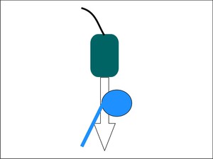
Fig. 19: Edge shadowing artifact - A lateral acoustic shadow (blue line) is produced by physical interactions of the ultrasound beam at cyst walls.
References: Adriana Calin, Cluj-Napoca
Recognition: It appears as narrow hypoechoic bands at the edges of cystic structures,
mainly with a divergent pattern.
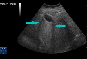
Fig. 7: Oblique abdominal scan - hypoechoic bands, representing edge shadowing artifact (blue arrow), at the margins of a cystic lesion.
Significance: This artifact is useful in diagnosing cysts but can also mimic stones,
especially in the gallbladder fundus and the cystic duct.
Improvement: A real image can be obtained by double-check in a second scan plane.
Acoustic enhancement (increased through transmission) artifact
When the ultrasound beam encounters a focal weakly attenuating structure,
the amplitude of the beam beyond this structure is relatively increased than the beam amplitude of the surrounding tissue at the same depth.
The echoes returning from structures deep to the focal weak attenuator are of higher amplitude and consequently displayed falsely as more echogenic.
Actually,
the focal weak structure only attenuates the sound less than the surrounding tissue.
TGC is responsible for the uniformization of the tissue echoes and for the overcompensation through the liquid structure,
causing the deeper echoes to be brighter.
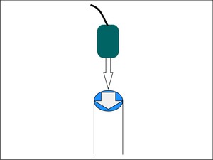
Fig. 20: Acoustic enhancement - The echoes received distally to a weak attenuating tissue (blue structure) are higher in intensity than echoes received from a similar depth.
References: Adriana Calin, Cluj-Napoca
Recognition: Increased through transmission is displayed as a bright band extending from a structure of low attenuation,
such as cysts,
abscesses or necrotic lesions.
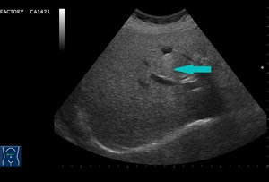
Fig. 8: Transverse section - hyperechoic band (blue arrow) extending from a cystic lesion - acoustic enhancement artifact
Significance: This artifact increases confidence in the diagnosis of a cyst or other anechoic structures,
but can be troublesome in evaluating areas behind liquid lesions.
Improvement: This artifact depends on the frequency of the ultrasound beam,
attenuation being greater with increase in frequency.
Different tissues encountered by the ultrasound beam attenuate the beam differently.
If the attenuation coefficient is high,
for instance in fat,
the beam may not fully penetrate the imaging field and the deeper structures may not be visualized.
The transducer with the most appropriate frequency should be then selected to enrich penetration.
Color Artifacts
Many color artifacts can adversely affect or distort the interpretation of color Doppler signal findings.
Some are unavoidable and can actually be used to enhance the accuracy and sensitivity of the diagnosis.
Noise is caused by setting the color gain too high and it is considered to be troublesome.
In some cases,
it can be useful in detecting slow flow.
Motion artifacts,
also known as color flash,
represent another unwanted image.
They occur due to transmitted cardiac pulsations (vascularized masses in the left lobe of the liver) or due to transmitted aortic pulsations.
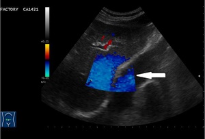
Fig. 9: Doppler signal (white arrow) caused by cardiac pulsations projected falsely in the right lobe of the liver - motion artifact.
Aliasing happens when the Nyquist limit is exceeded,
causing ambiguity on color Doppler images. The Nyquist limit represents half of the pulse repetition frequency,
at which the transmitter sends out pulses.
Aliasing occurs when the Doppler frequency exceeds half of the pulse repetition frequency,
leading to a color reversal to the ultrasound image. This artifact can be prevented by increasing the pulse repetition frequency.
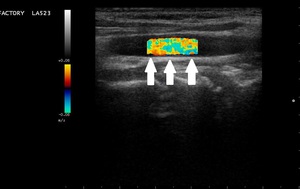
Fig. 10: Longitudinal view of the carotid artery - reverse signal (white arrows) - aliasing.
The twinkling artifact has a major diagnostic significance.
It represents a focus of alternating colors in Doppler signal behind a reflective object,
especially calculi,
giving the appearance of turbulent blood flow.
In enhances accuracy and sensitivity in the diagnostic of nephrolitiasis,
urolithiasis and billiary lithiasis.
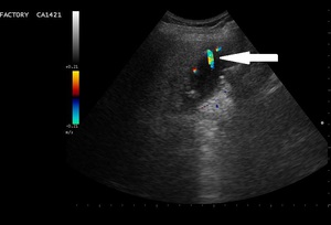
Fig. 11: Alternation of colors (white arrow) behind a strong reflector (billiary lithiasis)- twinkling artifact.
The confetti artifact consists in multiple small color pixels,
being an important sign of abnormality,
such as turbulent flow past a stenosis.

, the echoes generated by it are falsely displayed as overlapping the object of interest (green square). References: Adriana Calin, Cluj-Napoca")
.")
 within the center of the focal zone, the falsely displayed echoes generated by the peripheral object (purple circle) will disappear. References: Adriana Calin, Cluj-Napoca")
, encounter and object (purple square), the machine assumes that the corresponding returning echoes come from the main beam. Therefore, on the display, the object appears misplaced and duplicated. References: Adriana Calin, Cluj-Napoca")
.")
 will be repeatedly reflected. References: Adriana Calin, Cluj-Napoca")
.")
.")

, an alternative path (purple arrows) encounters a deeper reflective interface first. The resulting echoes from the alternative path take longer to return to the transducer and are erroneously placed on the display. References: Adriana Calin, Cluj-Napoca")
, while the duplicated echogenic one is projected in the expected lung area, equidistant from the diaphragm (pink arrow).")
 are lower in intensity in comparison to other echoes received from similar depth. References: Adriana Calin, Cluj-Napoca")
 in a case of gallstones.")
 is produced by physical interactions of the ultrasound beam at cyst walls. References: Adriana Calin, Cluj-Napoca")
, at the margins of a cystic lesion.")
 are higher in intensity than echoes received from a similar depth. References: Adriana Calin, Cluj-Napoca")
 extending from a cystic lesion - acoustic enhancement artifact")
 caused by cardiac pulsations projected falsely in the right lobe of the liver - motion artifact.")
 - aliasing.")
 behind a strong reflector (billiary lithiasis)- twinkling artifact.")