1.
US artifacts associated with ultrasound beam characteristics:
Image processing assumes that the echoes detected originate from within the main ultrasound beam.
The ultrasound beam is not uniform with depth,
the main beam leaves the transdurer with the same width as it,
then narrows as it approaches the focal zone and widens again distal to this zone.
1.1.
Beam width artifact: Fig. 8
A reflective object is located beyond the widened ultrasound beam,
afther the focal zone,
creates false detectable echoes that are displayed as overlapping the structure of interest.
Usually,
it occurs when scanning an anechoic structure and some periphereal echoes are idetntified,
i.e.
gas bubbles in the duodenum simulating small gallstones and peripheric echoes in the bladder.
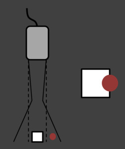
Fig. 1
|
How to avoid:
- Adjusting the focal zone to the depth level of interest.
- Placing the transducer at the center of the object being studied.
|
1.2.
Side lobe artifact: Fig. 9
Side lobes are multiple beams of low-amplitude ultrasound energy that project radially from the main beam axis and are seen primarily in linear-array transducers.
Strong reflectors present in the path of these side lobes,
outside of the central beam,
may create echoes detectable by the transducer that are displayed as if they originated from within the central beam.
It recognized as echogenic,
linear or curvilinear echoes present within an expected anechoic structure such as the gallbladder or urinary bladder,
as with beam width artifact.
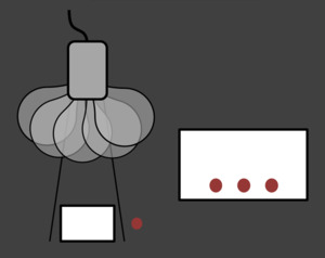
Fig. 2
|
How to avoid:
- Adjusting the focal zone to the depth level of interest.
- Placing the transducer at the center of the object being studied.
|
2.
US artifacts associated with multiple echoes:
US assumes that an echo returns to the transducer after a single reflection and that the depth of an object is related to the time for this round trip.
2.1.
Reverberation artifact: Fig. 10
It occurs when an ultrasound beam encounters two strong parallel reflectors.
When the ultrasound beam reflects back and forth between the reflector,
the US transducer interprents the sound waves returning has deeper structures since it took longer for the wave to return to the transducer.
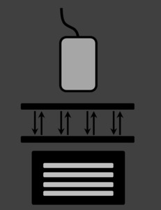
Fig. 3
|
How to avoid:
- Changing the angle of insonation so that reverberation between strong parallel reflectors cannot occur.
|
2.2.
Comet tail artifact: Fig. 11
It is a form of reverberation. In this case,
the two reflective interfaces and thus sequential echoes are closely spaced. Therefore,
the sequential echoes may be so close together that individual signals are not perceivable.
|
This finding is seen when scanning small calcific,
crystalline,
highly reflective objects,
as the following:
- Small renal or ureteric calculi.
- Small commom bile duct stones.
- Adenomyomatosis of the gallbladder.
- Pancreatic calcifications of chronic pancreatitis.
- Testicular microlithiasis (sometimes).
- Thyroid colloid nodules.
- Foreign bodies (surgical clips,
catheter tips,
debris,
glass,
metal).
|
2.3.
Ring down artifact: Fig. 12
In the past,
ring-down artifact has been thought to be a variant of comet tail artifact based on the similar appearance of the two artifacts,
but it is produced by a different mechanism.
It occurs when ultrasound energy causes resonant vibrations within fluid trapped between a tetrahedron of air bubbles.
These vibrations create a continuous sound wave that is transmitted back to the transducer.
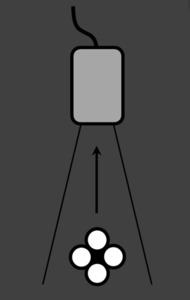
Fig. 4
2.4.
Mirror image artifact: Fig. 13
This artifact occurs when there is a highly reflective suface (i.e.
diaphragm) in the path of the primary beam.
The US beam reflects from a such a suface but instead of directly being received by the transducer,
it encounters anocher structure (i.e.
nodular lesion) and is reflected back to the highly reflective surface.
It then again reflects back towards the transducer.
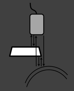
Fig. 5
The ultrasound machine makes a false assumption that the returning echo has been reflected once and hence the delayed echos are judged as if being returned from a deeper structure,
thus giving a mirror artifact on the other side of the reflective surface.
3.
US artifacts associated with velocity errors:
The speed of sound within a material is dependent on its density and elastic properties.
Density and speed of US for selected tissues
| Material |
Density (kg/m3) |
Velocity (m/sec) |
|
Air
Fat
Soft tissues
Bone
|
1.2
924
1050
1912
|
330
1450
1540
4080
|
However,
US image processing assumes a constant speed of sound in human tissue of 1540 m/sec.
3.1.
Speed displacement artifact:
When sound travels through material with a velocity significantly slower than the assumed 1450 m/sec,
the returning echo will take longer to return to the transducer.
The image processor assumes that the length of time for a single round trip of an echo is related only to the distance traveled by the echo.
The echoes are thus displayed deeper on the image than they really are.
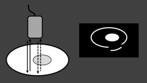
Fig. 6
A commonly encountered scenario is speed displacement artifact due to slowing of the ultrasound beam by focal fat.
3.2.
Refraction artifact:
This artifact occurs when a transmitted US pulse strikes an interface at non-perpendicular angle between two adjacent tissues with different density.
When this occurs,
the incident ultrasound beam changes direction.
The degree of this change in direction is dependent on both the angle of the incident ultrasound beam and the difference in velocity between the two tissues.
This relationship is described by Snell’s law:
sinθr / sinθi = c2 / c1
where c = velocity,
i = incidence,
and r = refraction.
The image processing assumes that the beam travels in a straight line and thus misplaces the returning echoes to the side of their true location.
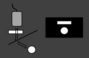
Fig. 7
This artifact may be recognized in pelvic structures deep to the junction of the rectus muscles and midline fat.
|
How to avoid:
- Moving the transducer such that the incident pulse is perpendicular to the interface.
|
4.
US artficats associated with attenuation errors:
As an ultrasound beam travels through the body, its energy becomes attenuated secondary to absorption and scatter.
4.1.
Acoustic shadowing: Fig. 14
When the ultrasound beam encounters a strongly attenuating or highly reflective structure,
the amplitude of the beam distal to this structure is diminished.
This phenomenon is recognized as a dark or hypoechoic band known as a “shadow” deep to a highly attenuating structure.
It happens most frequently with solid structure,
as sound conducts most rapidly in areas where molecules are closely packed,
such as in bone o stones.
4.2.
Acoustic enhacement (posterior enhancement or enchanced through transmission): Fig. 15
When the ultrasound beam encounters a focal weakly attenuating structure,
the amplitude of the beam beyond this structure is greater than the beam amplitude at the same depth in the rest of the field.
We identify this “increased through transmission” as a bright band extending from an object of low attenuation.
This is characteristic of fluid filled structures such as cysts,
the urinary bladder and the gallbladder.
Some solid masses,
especially lymphoma,
may also show acoustic enhancement posteriorly.
An echo that travels a greater distance in the body will be attenuated more than an echo of similar energy that travels a shorter path.
Ultrasound processing incorporates “compensation amplification” of echoes that take longer to return to the transducer.
In this process,
the echoes that return later are amplified more than earlier returning echoes.
This serves to make the image appear more uniform in the deep field.
“Time gain compensation” refers to a user-adjustable form of compensation.
5.
US artifacts associated with Doppler mode:
5.1.
Twinkling and colour comet tail artifacts: Fig. 16
We identify twinkling artifact as a focus of alternating colors on Color Doppler mode behind a reflective object (such as calculi),
which gives the appereance of turbulent blood flow.
This artifact is more sensitive for detection of small stones (i.e.
urolithiasis or cholelithiasis) than is acoustic shadowing,
especially if their surface is rough.
|
How to improve twinkling artifact for diagnosis:
- When the focal zone is located below a rough reflecting surface,
the twinkling artifact becomes more obvious.
- A lower pulse repetition frequency (PRF) facilitates its visualization.
|
It appears with or without an associated color comet-tail artifact.
This artifact,
which resembles the grey-scale comet-tail artifact,
appears as tail of linear band of alternating colors that extends away from the highly reflective structure.
5.2.
Pseudo-flow artifact: Fig. 17
Pseudoflow is related to motion and appears similar to real blood flow at color or power Doppler US,
but in the absence of a vascular structure.
The color or power Doppler signal will appear as long as the fluid motion continues.
Pseudoflow may be caused by the motion of ascites or urine.
Spectral analysis reveals flow that is atypical for a normal vessel.
5.3.
Aliasing artifact: Fig. 18
Aliasing is a common artefact in color and spectral Doppler ultrasound.
It is cause by blood flow velocity exceeding the upper limits of the scale (the maximum velocity that can be displayed is limited by the pulse repetition frecuency (PRF).
If the PRF is too low,
aliasing artifact may appear).
The artifact disappears if the upper margin of the velocity sale is increased above the peak flow velocity.
In color Doppler:
In color Doppler,
aliasing appears as red to blue colours mixed in a vessel (this is unlike in case of true reversal flow).
Aliasing is useful for detecting foci of increased flow (i.e.
stenosis,
arteriovenous fistula).
|
How to avoid aliasing in color Doppler:
|
In spectral Doppler:
In spectral Doppler,
aliasing appears as the velocity peak is cut off at the peak of the scale,
and the peak is displayed at the bottom of the scale.
|
How to avoid aliasing in spectral Doppler:
- Increasing the PRF.
- Lowering the baseline.
- Increasing the Doppler angle.
|
Aliasing does not occur with power Doppler,
as it does not dipslay velocity.


