ECR 2020 / C-15006
Emergency cervical spine trauma: Spectrum of injuries and Imaging pictorial review
Congress:
ECR 2020
Poster Number:
C-15006
Type:
Educational Exhibit
Keywords:
Performed at one institution, Not applicable, Trauma, Education, Digital radiography, CT, Emergency, Emergency Imaging
Authors:
L. Garg1, P. jain2, S. B. Grover1, M. Sinha1; 1New Delhi/IN, 2Delhi, Delhi/IN
DOI:
10.26044/ecr2020/C-15006

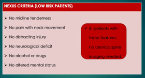
Table 1:
NEXUS Criteria

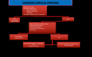
Table 2:
Canadian C spine rule

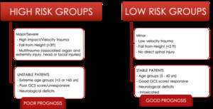
Table 3:
High and Low risk Groups

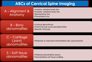
Table 4:
ABCs approach to cervical spine imaging evaluation.

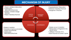
Table 5:
Mechanism of Injuries

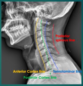
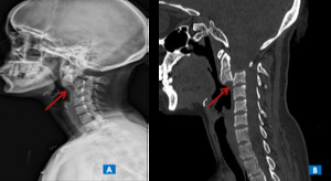
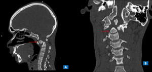
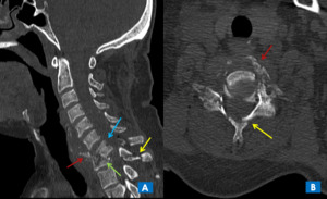
Fig. 1:
Spinal lines
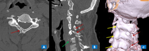
, and sagittal CT image(B), shows
A (Alignment) – Discontinuity of anterior, posterior vertebral lines and spinolaminar lines
B (Bones) - Anterolisthesis of C5 over C6 (yellow arrow) with perched unilateral facet joint with small chip fracture of inferior facet of C5 (red arrows) with fracture of spinous process of C6 vertebra (blue arrow) - UNILATERAL FACETAL DISLOCATION
C (Cartilage) – Decreased intervertebral disc space between C5-C6.
S (Soft tissues) – Prevertebral and paravertebral soft tissue appear normal.")
Fig. 2:
Sagittal plain radiograph (A), and sagittal CT image(B), shows
A (Alignment)...
 – Discontinuity of anterior and posterior vertebral lines.
B (Bones) - Comminuted fracture of C7 vertebral body with anteriorly displaced tear drop fragment from anteroinferior aspect of vertebral body(blue arrow) and posterior displacement of large posterior part of vertebral body into the spinal canal (red arrow).
C (Cartilage) – Decreased IVD space between C6-C7 and C7-T1.
S (Soft tissues) – Widening of prevertebral space at C7 level")
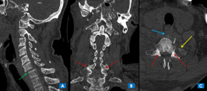
Fig. 3:
TEARDROP FRACTURE - Sagittal CT image, shows
A (Alignment) – Discontinuity...
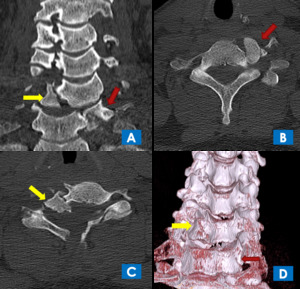
, Coronal CT (B), and axial CT (C) images show-
A (Alignment) – Discontinuity of anterior, posterior vertebral and posterior spinous lines
B (Bones) - Anterolisthesis of C6 over C7 (green arrow) with perched bilateral facet joints (red arrows) with fracture of left lateral mass of C7 vertebra involving foramen transversarium (yellow arrow) with fracture of vertebral body (blue arrow)
C (Cartilage) – Dislocation of bilateral facetal joints. (Red arrows)
S (Soft tissues) – Prevertebral and paravertebral soft tissue appear widened.")
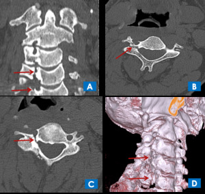
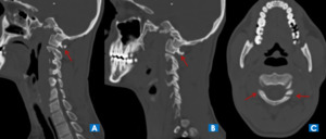
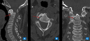
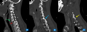
Fig. 4:
BILATERAL FACETAL JOINT DISLOCATION - Sagittal CT image(A), Coronal CT (B), and...

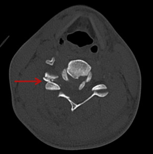
Fig. 5:
UNILATERAL FACETAL DISLOCATION - Axial CT image showing classical HAMBURGER...
 show-
A (Alignment) – Discontinuity of anterior, posterior vertebral lines
B (Bones) - Anterolisthesis of C6 over C7 with wedge fracture of C7 vertebra (red arrow) with locked facetal joint (blue arrow) with chip fracture of superior articular facet of C7 vertebra (yellow arrow) - UNILATERAL FACETAL JOINT DISLOCATION
C (Cartilage) – Reduced IVD space with dislocation of facetal joint.
S (Soft tissues) – Qwidening of prevertebral space with air foci noted (green arrow)")
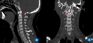
Fig. 6:
Sagittal CT images(A, B, C) show-
A (Alignment) – Discontinuity of anterior,...
, and sagittal CT image(B), shows
A (Alignment) – Disruption of the anterio and posterior cortex lines with maintained spinolaminar lines
B (Bones) - Spondyloptosis of C2 over C3 (red arrows)
C (Cartilage) – Disruption of intervertebral disc space and facetal joints at C2-C3 level.
S (Soft tissues) – Prevertebral and paravertebral soft tissue appear normal.")
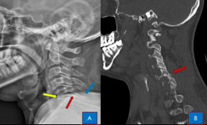
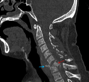
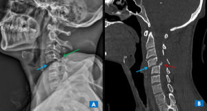
Fig. 7:
HANGMAN'S FRACTURE - Sagittal plain radiograph (A), and sagittal CT image(B),...
, and sagittal CT image(B), shows
A (Alignment) – Discontinuity of anterior, posterior vertebral and spinolaminar lines
B (Bones) - Anterolisthesis of C4 over C5 (blue arrow) with locked bilateral facetal joints (green arrows). Sagittal CT image (B) of the same patient shows the C4 burst fracture. Additionally a small posterior retropulsed fracture fragment is seen within the spinal canal (red arrow), which is missed on plain radiograph.
C (Cartilage) – Decreased intervertebral disc space between C4-C5 and bilateral facetal dislocation.
S (Soft tissues) – Prevertebral and paravertebral soft tissue appear normal.")
Fig. 8:
COMPRESSION/BURST FRACTURE - Sagittal plain radiograph (A), and sagittal CT...
 and coronal (B) CT images, show-
A (Alignment) – Disruption of the anterio and posterior cortex lines with maintained spinolaminar and posterior spinous lines
B (Bones) – Linear fracture of tip of odontoid process of C2 vertebra with mildlly anteriorly displaced fractured fragment (red arrows)
C (Cartilage) – IVD spaces and facetal joints appear normal.
S (Soft tissues) – Prevertebral and paravertebral soft tissue appear normal.")
Fig. 9:
Type 1 odontoid fracture – Sagittal (A) and coronal (B) CT images, show-
A...
, coronal (B) and axial (C) CT images, shows
A (Alignment) – Disruption of the anterior and posterior cortex lines with maintained spinolaminar and posterior spinous lines
B (Bones) – Linear fracture of tip of odontoid process of C2 vertebra with anteriorly displaced and angulated fractured fragment (red arrows)
C (Cartilage) – IVD spaces and facetal joints appear normal.
S (Soft tissues) – Prevertebral and paravertebral soft tissue appear normal.")
Fig. 10:
Type 1 odontoid fracture – Sagittal (A), coronal (B) and axial (C) CT images,...
 and coronal (B) CT images, show-
A (Alignment) – Disruption of the anterior and posterior cortex lines with maintained spinolaminar and posterior spinous lines
B (Bones) – Fracture of odontoid process at dens-body junction of C2 vertebra with anteriorly displaced and angulated fractured fragment (red arrows)
C (Cartilage) – IVD spaces and facetal joints appear normal.
S (Soft tissues) – Prevertebral and paravertebral soft tissue appear normal.")
Fig. 11:
Type II odontoid fracture – Sagittal (A) and coronal (B) CT images, show-
A...
, Axial (B) and coronal (C) CT images, show-
A (Alignment) – Disruption of the anterior and posterior cortex lines with maintained spinolaminar and posterior spinous lines
B (Bones) – Fracture of odontoid process with fracture of C2 vertebral body with anterioinferiorly displaced fractured fragment (red arrows)
C (Cartilage) – IVD spaces and facetal joints appear normal.
S (Soft tissues) – Prevertebral and paravertebral soft tissue appear normal.")
Fig. 12:
Type III odontoid fracture – Sagittal (A), Axial (B) and coronal (C) CT...
, Sagittal (A), and 3D reconstructed VRT(C) CT images, show-
A (Alignment) – Disruption of spinolaminar and posterior spinous lines
B (Bones) – Fracture of lamina of C4 and C5(red arrows). There is anterior wedge fracture of C6 vertebral body with mild posterolisthesis of C6 over C7 (green arrow)
C (Cartilage) – IVD spaces and facetal joints (yellow arrows) appear normal.
S (Soft tissues) – Prevertebral and paravertebral soft tissue appear normal.")
Fig. 13:
Axial (A), Sagittal (A), and 3D reconstructed VRT(C) CT images, show-
A...
, axial (B and C), and 3D reconstructed VRT(D) CT images, show-
A (Alignment) – Alignement not maintained
B (Bones) – Fracture of pedicle of C4, C5 vertebral bodies with involvement of vertebral foramen(red arrows).
C (Cartilage) – IVD spaces appear normal.
S (Soft tissues) – Prevertebral and paravertebral soft tissue appear normal.")
Fig. 14:
ROTATIONAL INJURY - Coronal (A), axial (B and C), and 3D reconstructed VRT(D)...
, axial (B and C), and 3D reconstructed VRT(D) CT images, show-
A (Alignment) –Disruption of alignment of cervical spine.
B (Bones) – Comminuted fracture of C6 vertebral body with superiorly displaced right fractured fragment (yellow arrows), and inferiorly displaced left fractured fragment (red arrows), which are seen lying adjacent to C5 and C7 vertebral bodies. There is associated fracture of pedicle of C4, C5 vertebral bodies (blue arrows)
C (Cartilages) – Disruption of C5-C6 and C6-C7 IVD space.
S (Soft tissues) – Prevertebral and paravertebral soft tissue show swelling in form of loss of fat planes.")
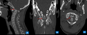
Fig. 15:
COMPRESSION FRACTURE WITH ROTATIONAL/HYPERFLEXION INJURY- Coronal (A), axial (B...
, and axial (C) CT images, show-
A (Alignment) –Disruption of spinolaminar line.
B (Bones) – Linear fracture of posterior arch of C1 vertebra (red arrows).
C (Cartilages) – IVD spaces appear normal
S (Soft tissues) – Prevertebral and paravertebral soft tissue appear normal")
Fig. 16:
JEFFERSON'S FRACTURE - Coronal (A and B), and axial (C) CT images, show-
A...
, axial (C) Coronal (D), CT images, show-
A (Alignment) –Disruption of posterior vertebral body line.
B (Bones) – Linear fracture of body of C2 vertebra (red arrows) extending to pedicle without involvement of dens or dens-body junction. No listhesis of vertebral body noted.
C (Cartilages) – IVD spaces appear normal
S (Soft tissues) – Prevertebral and paravertebral soft tissue appear normal.")
Fig. 17:
NON ODONTOID NON HANGMAN FRACRTURE - Sagittal (A and B), axial (C) Coronal (D),...
, axial (B) and coronal (C) CT images, shows
A (Alignment) – Discontinuity of spino-laminar and posterior spinous lines
B (Bones) - Comminuted fracture of left lateral mass, lamina and spinous process of C7 vertebra (red arrows).
C (Cartilage) – C6-C7 facetal joint dislocation with fracture.
S (Soft tissues) – Fat planes lost in paravertebral soft tissue.")
Fig. 18:
Sagittal (A), axial (B) and coronal (C) CT images, shows
A (Alignment) –...
 –Disruption of posterior vertebral body line and spinolaminar line.
B (Bones) – Fracture of pedicle of C6 vertebra (red arrow) with anterior displacement of posterior elements. No listhesis of vertebral body noted.
C (Cartilages) – Facetal joint dislocation.
S (Soft tissues) – Prevertebral and paravertebral soft tissue show swelling.")
Fig. 19:
Sagittal CT image, show-
A (Alignment) –Disruption of posterior vertebral...
 and axial (B) CT image, shows
A (Alignment) – Discontinuity of anterior, posterior vertebral lines, spinolaminar and posterior spinous line.
B (Bones) - Comminuted fracture of C7 vertebral body with anteriorly displaced tear drop fragment from anteroinferior aspect of vertebral body(red arrows) and posterior displacement of large posterior part of vertebral body into the spinal canal (blue arrow). There is associated comminuted fracture of posterior elements of C7 verterba (yellow arrows) and wedge fracture of anterior end plate of T1 vertebra (green arrow).
C (Cartilage) – Decreased IVD space between C6-C7 and C7-T1.
S (Soft tissues) – Widening of prevertebral space at C7 level with fractured fragments in prevertebral space.")
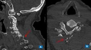
Fig. 20:
TEARDROP FRACTURE - Sagittal (A) and axial (B) CT image, shows
A (Alignment)...
, and axial CT image(B), shows
A (Alignment) – Discontinuity of spinolaminar and posterior spinous lines
B (Bones) - Comminuted fracture of right lateral mass, bilateral lamina and spinous process of C7 vertebra (red arrows).
C (Cartilage) – C6-C7 facetal joint dislocation with fracture.
(Soft tissues) – Fat planes lost in paravertebral soft tissue.")
Fig. 21:
CLAY SHOVELER FRACTURE - Sagittal (A), and axial CT image(B), shows
A...
.")
Fig. 22:
BURST FRACTURE - Anteroposterior cervical radiograph shows burst fracture of C6...